Cutter bending machine of roller cutter die

A technology of roller knife and mold bending, which is applied in the direction of feeding device, positioning device, storage device, etc., can solve the problems of inconvenient processing, achieve the effect of convenient processing, wide application, and guaranteed stability

Active Publication Date: 2019-06-25
深圳市骏昊自动化科技有限公司
View PDF10 Cites 3 Cited by
  • Summary
  • Abstract
  • Description
  • Claims
  • Application Information

AI Technical Summary

Problems solved by technology

[0004] For this reason, the technical problem to be solved by the present invention is to overcome the technical defect of inconvenient processing that the curved knife machine of the prior art can only choose one to process a straight blade or an arc blade when making a roller die, thereby providing A Roller Die Scimitar Machine with Convenient Processing and High Efficiency

Method used


Image

  • Cutter bending machine of roller cutter die
  • Cutter bending machine of roller cutter die
  • Cutter bending machine of roller cutter die

Examples


Embodiment Construction

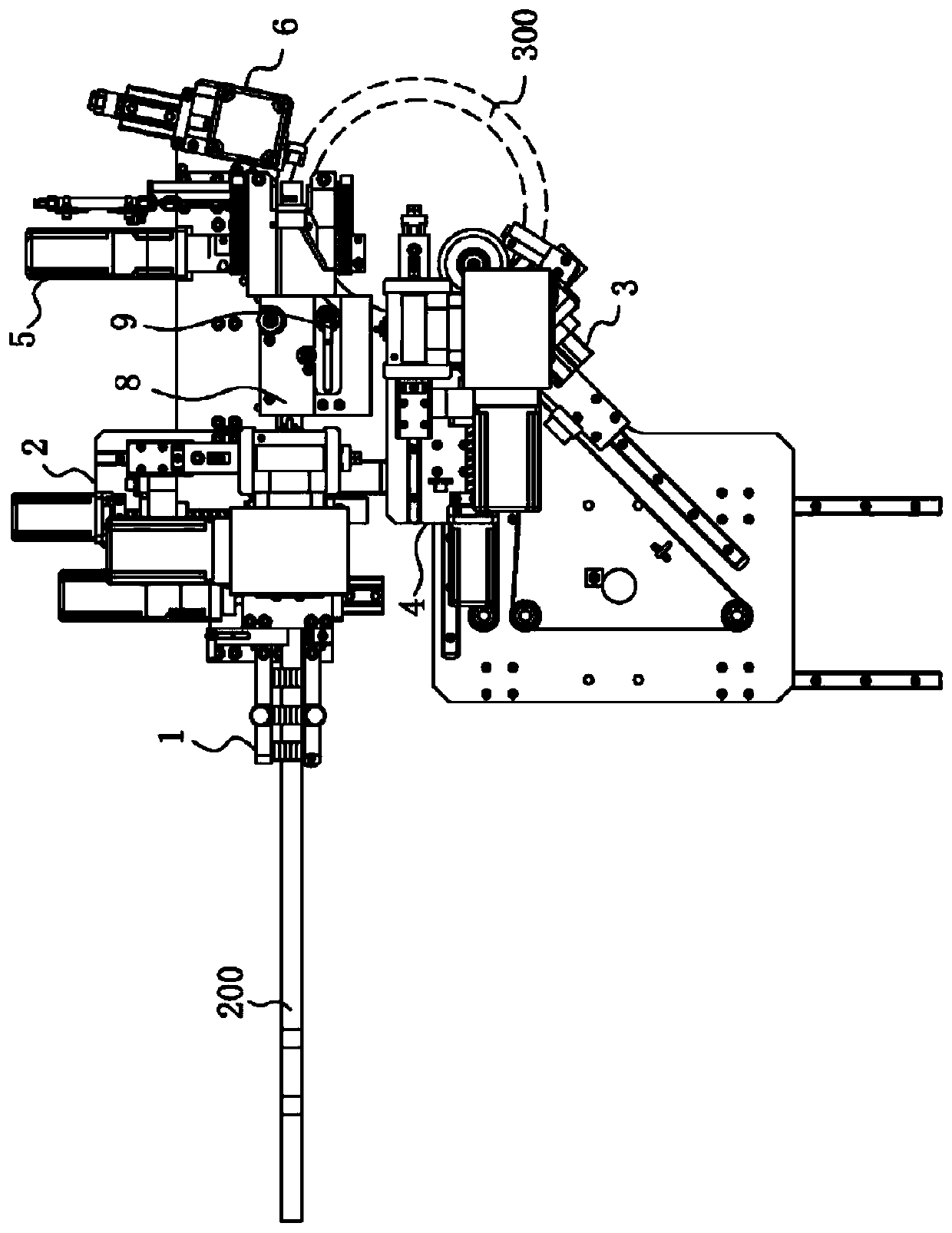
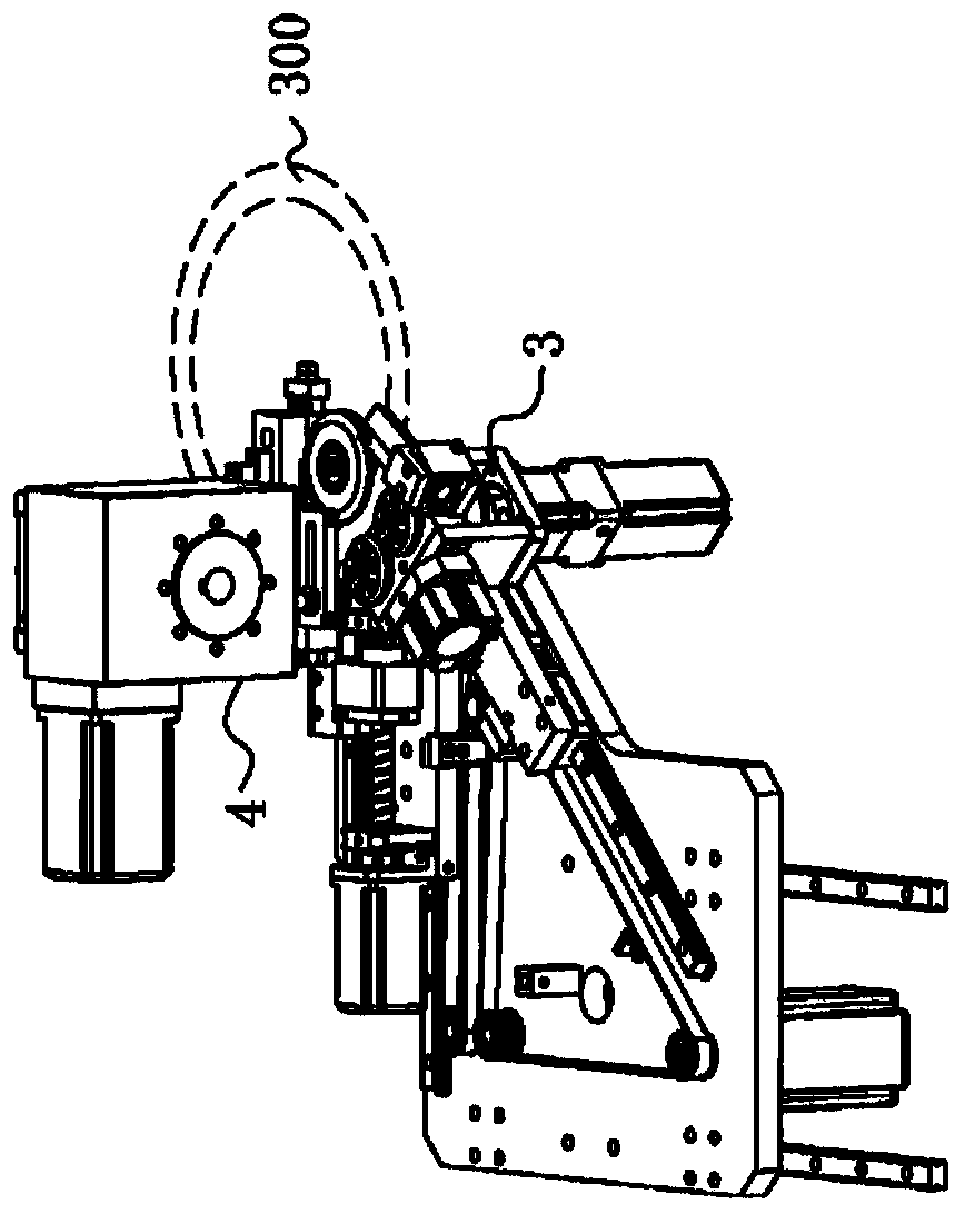
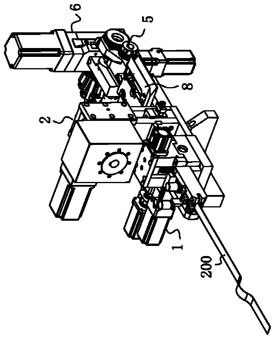
[0031] The technical solutions of the present invention will be clearly and completely described below in conjunction with the accompanying drawings. Apparently, the described embodiments are some of the embodiments of the present invention, but not all of them. Based on the embodiments of the present invention, all other embodiments obtained by persons of ordinary skill in the art without making creative efforts belong to the protection scope of the present invention.

[0032] In the description of the present invention, it should be noted that the orientation or positional relationship indicated by the terms "upper", "lower" and "outer" are based on the orientation or positional relationship shown in the drawings, and are only for the convenience of describing the present invention and simplified descriptions, rather than indicating or implying that the device or element referred to must have a specific orientation, be constructed and operate in a specific orientation, and th...


PUM


Abstract

The invention provides a cutter bending machine of a roller cutter die. The cutter bending machine is suitable for integral machining of a straight blade and an arc blade and comprises a straight blade front end machining structure, an arc blade front end machining structure and a rear end machining structure. The straight blade front end machining structure comprises a straight blade feeding device and a straight blade punching device so as to feed and punch the straight blade. The arc blade front end machining structure comprises an arc blade feeding device and an arc blade punching device so as to feed and punch the arc blade. The discharging end of the straight blade front end machining structure and the discharging end of the arc blade front end machining structure are connected withthe feeding end of the rear end machining structure. The rear end machining structure comprises a bending device and a shearing device, and then the punched straight blade and arc blade can share thebending device and the shearing device. Under the condition without adjusting, the straight blade or the arc blade is selectively machined. The cutter bending machine of the roller cutter die achievesintegral machining of the straight blade and the arc blade, and the effects of convenient machining and high efficiency are brought.

Description

technical field [0001] The invention relates to the field of knife belt processing, in particular to a roller knife die bending machine. Background technique [0002] With the rapid development of electronics, printing and packaging industries, as its supporting industry - die-cutting board (mold cutting) processing industry has been greatly developed. At present, the die-cutting boards on the market are mainly to open the slit with the size of the die-cutting blade on a certain thickness of the board, and then insert the blade into the slit to achieve the purpose of die-cutting. It is generally divided according to the shape of the forming substrate. It is a flat pressing plate (flat die) and a round pressing plate (roller die). Since the round pressing plate rotates continuously when the drum is working, its production efficiency is high and it is widely used. The processing of the roller knife template is mainly to process the knife slits for installing the die-cutting b...

Claims


Application Information

Patent Timeline
Patent Type & Authority Applications(China)
IPC IPC(8): B21D5/06B21D28/14B21D43/00B21D43/02B21D43/28
Inventor 杨高瞻钟海凤刘勇
Owner 深圳市骏昊自动化科技有限公司
Why Eureka
Try Eureka