
Unmanned-aerial-vehicle holder protection device

A technology of protection device and machine platform, which is applied in the direction of aircraft indicating device, aircraft parts, aircraft lander, etc. It can solve the problems that the protective shell cannot protect the camera and affect the camera's field of view, so as to prolong the life, protect the platform and reduce the wear effect

Inactive Publication Date: 2019-06-25
芜湖市极星航空科技有限公司
View PDF0 Cites 0 Cited by
  • Summary
  • Abstract
  • Description
  • Claims
  • Application Information

AI Technical Summary

Problems solved by technology

[0004] The purpose of the present invention is to provide a UAV cloud platform protection device, which aims to improve the camera that cannot be protected by the protective shell in the prior art. Once the protective shell covers the camera, it will affect the camera during the rotation of the camera. problem of vision

Method used


Image

  • Unmanned-aerial-vehicle holder protection device
  • Unmanned-aerial-vehicle holder protection device
  • Unmanned-aerial-vehicle holder protection device

Examples


Embodiment Construction

[0017] In order to make the purpose, technical solutions and advantages of the embodiments of the present invention clearer, the technical solutions in the embodiments of the present invention will be clearly and completely described below in conjunction with the accompanying drawings in the embodiments of the present invention. Obviously, the described embodiments It is some embodiments of the present invention, but not all of them. Based on the implementation manners in the present invention, all other implementation manners obtained by persons of ordinary skill in the art without creative efforts fall within the protection scope of the present invention. Accordingly, the following detailed description of the embodiments of the invention provided in the accompanying drawings is not intended to limit the scope of the claimed invention, but merely represents selected embodiments of the invention. Based on the implementation manners in the present invention, all other implement...


PUM


Abstract

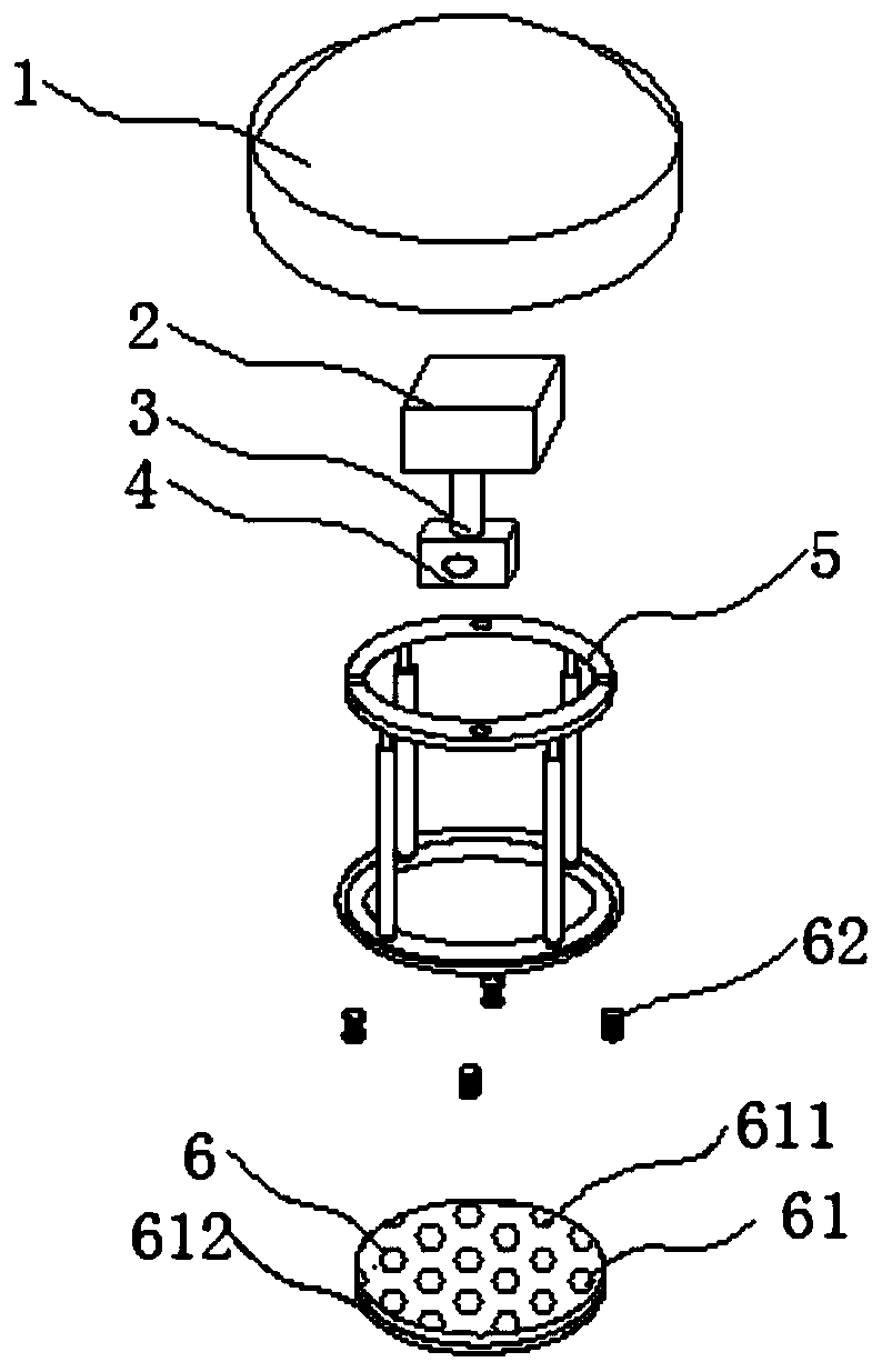
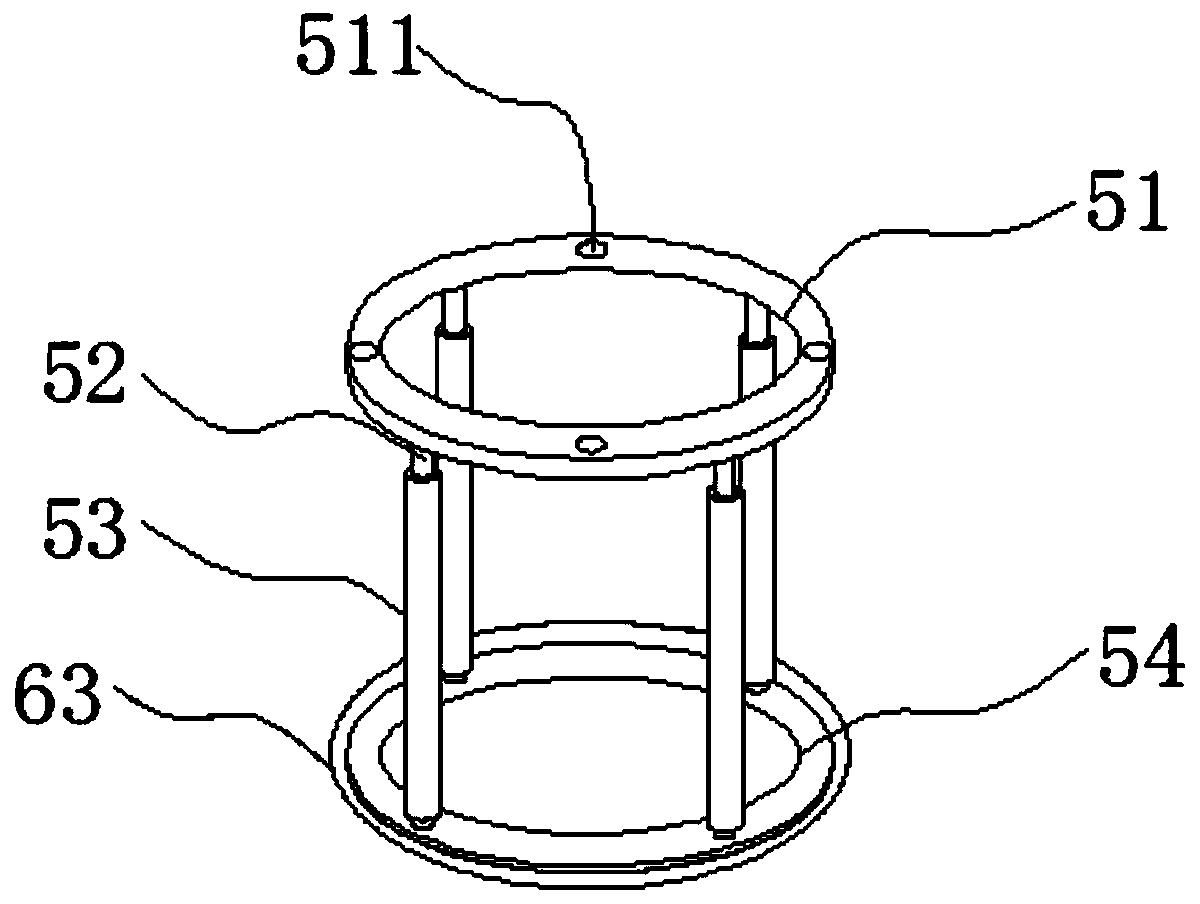
The invention discloses an unmanned-aerial-vehicle holder protection device. The unmanned-aerial-vehicle holder protection device comprises an unmanned-aerial-vehicle body, a holder body, a hanging rod, a camera, a protection mechanism and a shock absorption mechanism, wherein the holder body is fixed to the middle of the lower surface of the unmanned-aerial-vehicle body, a hanging rod is fixed tothe middle of the lower surface of the holder body, the camera is installed at the lower end of the hanging rod, the protection mechanism is arranged in the middle of the lower surface of the unmanned-aerial-vehicle body, is located outside the holder body, the handing rod and the camera, and comprises an upper installing ring and a lower installing ring, the lower installing ring is located below the upper installing ring, four standing columns are evenly fixed between the upper installing ring and the lower installing ring, and rollers are inserted to the circumferential outside of the standing columns. According to the unmanned-aerial-vehicle holder protection device, by arranging the protection mechanism, it can be avoided that external hard matter and the holder and the camera are collided in the flight process through the protection mechanism, sight of the camera cannot be blocked no matter how the holder rotates, the holder is protected, and the camera is also protected.

Description

technical field [0001] The invention relates to the technical field of unmanned aerial vehicle platforms, in particular to a protection device for unmanned aerial vehicle platforms. Background technique [0002] The gimbal is a mechanical component installed on the drone to mount the camera. The "stability" of the gimbal is the same. Generally, the gimbal of a drone can satisfy the three degrees of freedom of the camera: around the X, Y, and Z axes Rotation, each axis is equipped with a motor. When the drone is tilted, it will also cooperate with the gyroscope to strengthen the power in the opposite direction to the corresponding gimbal motor to prevent the camera from "tilting" with the drone, thereby avoiding camera shake. ; [0003] Because the UAV will encounter collisions during flight, there is a protective shell for the gimbal, but such a protective shell cannot protect the camera. Once the protective shell covers the camera, it will affect the rotation of the camera...

Claims


Application Information

Patent Timeline
Patent Type & Authority Applications(China)
IPC IPC(8): B64D47/08B64D45/06B64D45/00
Inventor 刘天天
Owner 芜湖市极星航空科技有限公司
Learn More