Flapping device for vertical wavy flange conveyer

A conveyor and corrugated technology, which is applied in the field of flapping devices of vertical corrugated sidewall conveyors, can solve the problem that the effect of vertical corrugated sidewall conveyors is not very obvious, and achieve the effects of increasing spacing and large flapping amplitude.

Inactive Publication Date: 2019-06-25
郎溪东奥输送装备科技有限公司
View PDF4 Cites 1 Cited by
  • Summary
  • Abstract
  • Description
  • Claims
  • Application Information

AI Technical Summary

Problems solved by technology

[0003] At present, the common cleaning measures for vertical corrugated sidewall conveyors include increasing the length of the head section and increasing the flapping cleaner on the return section of the head. Among them, the measure of "increasing the length of th...

Method used


Image

  • Flapping device for vertical wavy flange conveyer
  • Flapping device for vertical wavy flange conveyer
  • Flapping device for vertical wavy flange conveyer

Examples


Embodiment Construction

[0018] The present invention will be further described below in conjunction with the drawings.

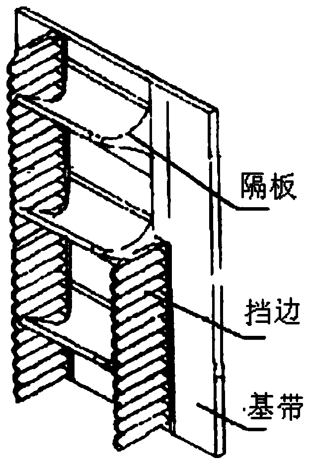
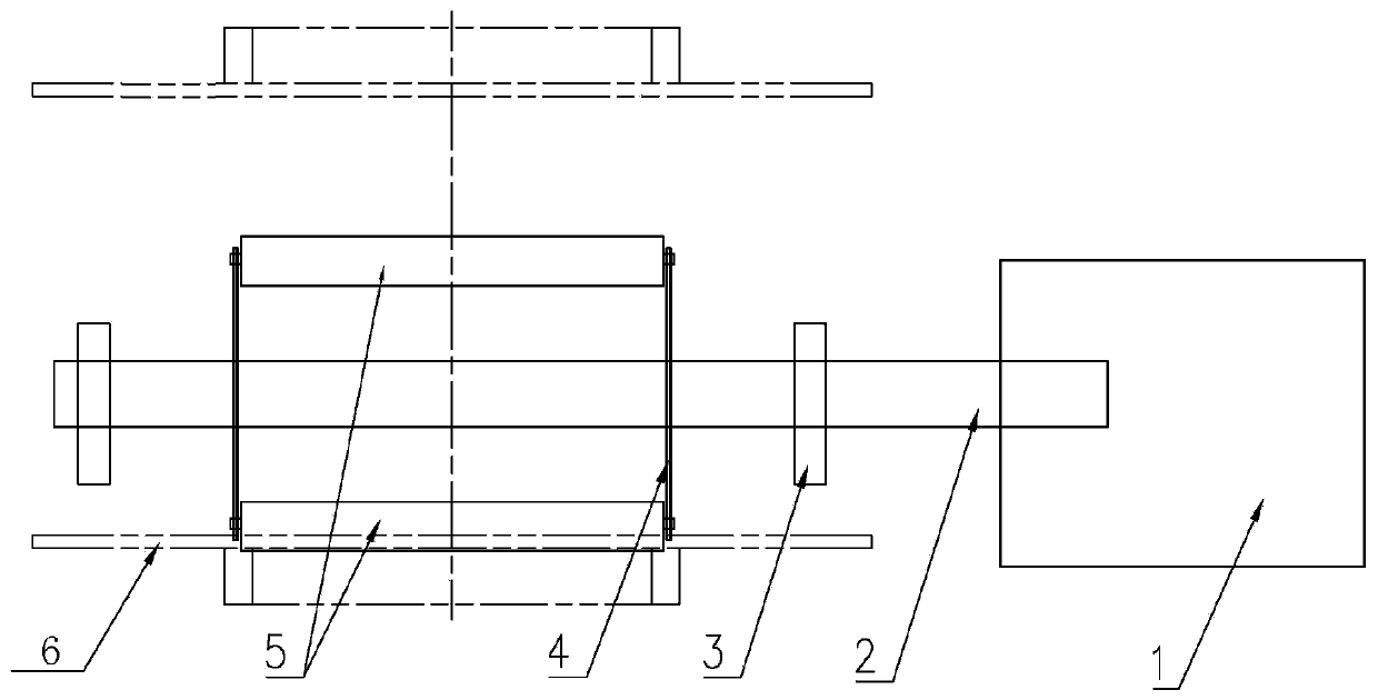
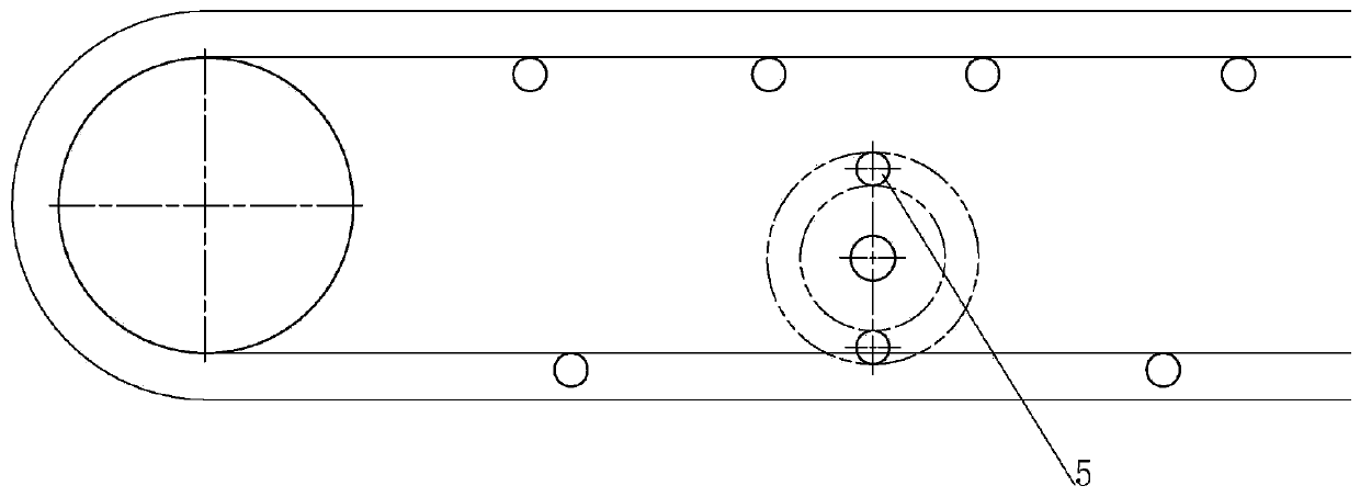
[0019] Such as Figure 3-Figure 4 As shown, a flapping device for a vertical corrugated sidewall conveyor includes a flapping device fixed above the tape under the vertical corrugated sidewall conveyor. The flapping device includes two roller racks 4 and two flapping rollers 5, two The roller racks are fixedly connected to the two sides of the two flapping rollers, and the two roller racks are coaxially connected with the two flapping rollers, and at least two roller racks penetrate a transmission shaft 2 and are fixed on the transmission shaft On the upper side, there are bearing seats 3 on both sides of the drive shaft. The bearing seats are fixed on the top of the tape 6 under the vertical wave-shaped rib conveyor through the frame of the vertical wave-shaped rib conveyor; one end of the drive shaft is fixed with a speed reducer Motor 1, the geared motor drives the transmission sh...


PUM


Abstract

The invention provides a flapping device for a vertical wavy flange conveyer. The flapping device comprises a flapping device unit fixed above a lower tape of the vertical wavy flange conveyer, and the flapping device unit comprises two carrier roller racks and two flapping carrier rollers; the two carrier roller racks are fixedly connected on the two sides of the two flapping carrier rollers separately; the two carrier roller racks are coaxially connected with the two flapping carrier rollers; at least two carrier roller racks penetrate into a transmission shaft and are fixed to the transmission shaft; bearing seats are arranged on the two sides of the transmission shaft; the bearing seats fix the transmission shaft above the lower tape of the vertical wavy flange conveyer through a rackof the vertical wavy flange conveyer; a deceleration motor is fixed to one end of the transmission shaft; and the deceleration motor drives the transmission shaft to anticlockwise rotate.

Description

Technical field [0001] The invention relates to the field of conveyors, in particular to a flapping device for a vertical corrugated sidewall conveyor. Background technique [0002] The vertical corrugated sidewall conveyor is mainly used for the vertical lifting of materials. It realizes continuous vertical transportation of materials through a relatively small horizontal space. Compared with ordinary horizontal transportation belt conveyors, the degree of use is not high. The reason is that The main one is the incomplete cleaning of the material. Due to the special nature of the belt, the corrugated sidewall conveyor cannot be cleaned by adding a cleaner in the return section like an ordinary conveyor belt. When the material is stuck on the corrugated sidewall tape Afterwards, a considerable part of the material was scattered intermittently in the return section, and it was generally concentrated at the lower belt of the tail of the return section. At the same time, due to the ...

Claims


Application Information

Patent Timeline
IPC IPC(8): B65G45/10
Inventor 舒新意孙方相李秀云季洪博
Owner 郎溪东奥输送装备科技有限公司
Why Eureka
Try Eureka