System for controlling civil engineering tool

A civil engineering and tool technology, applied in the field of controlling the working depth of civil engineering tools relative to cutting, can solve problems such as poor cutting depth, waste of civil engineering tool efficiency, waste of valuable materials, etc.

Inactive Publication Date: 2019-06-25
薛思源
View PDF0 Cites 0 Cited by
  • Summary
  • Abstract
  • Description
  • Claims
  • Application Information

AI Technical Summary

Problems solved by technology

[0003] Although the system of the '190 patent may automatically control the depth of cut of the civil engineering tool, it may undesirably control the civil engineering tool because the system of the '190 patent may not take into account the desired The difference in depth of cut between the ability of the jobsite to remove material
Specifically, the civil engineering tools of the '190 patent may be controlled to remove material that is desired to remain in the worksite, wasting valuable material and / or requiring replacement of material to achieve a desired grade
Additionally, the civil engineering tools of the '190 patent may be manipulated to remove less material from the worksite than intended, thereby wasting civil engineering tool efficiency

Method used


Image

  • System for controlling civil engineering tool

Examples


Embodiment Construction

[0008] The following will clearly and completely describe the technical solutions in the embodiments of the present invention with reference to the accompanying drawings in the embodiments of the present invention. Obviously, the described embodiments are only some, not all, embodiments of the present invention. Based on the embodiments of the present invention, all other embodiments obtained by persons of ordinary skill in the art without making creative efforts belong to the protection scope of the present invention.

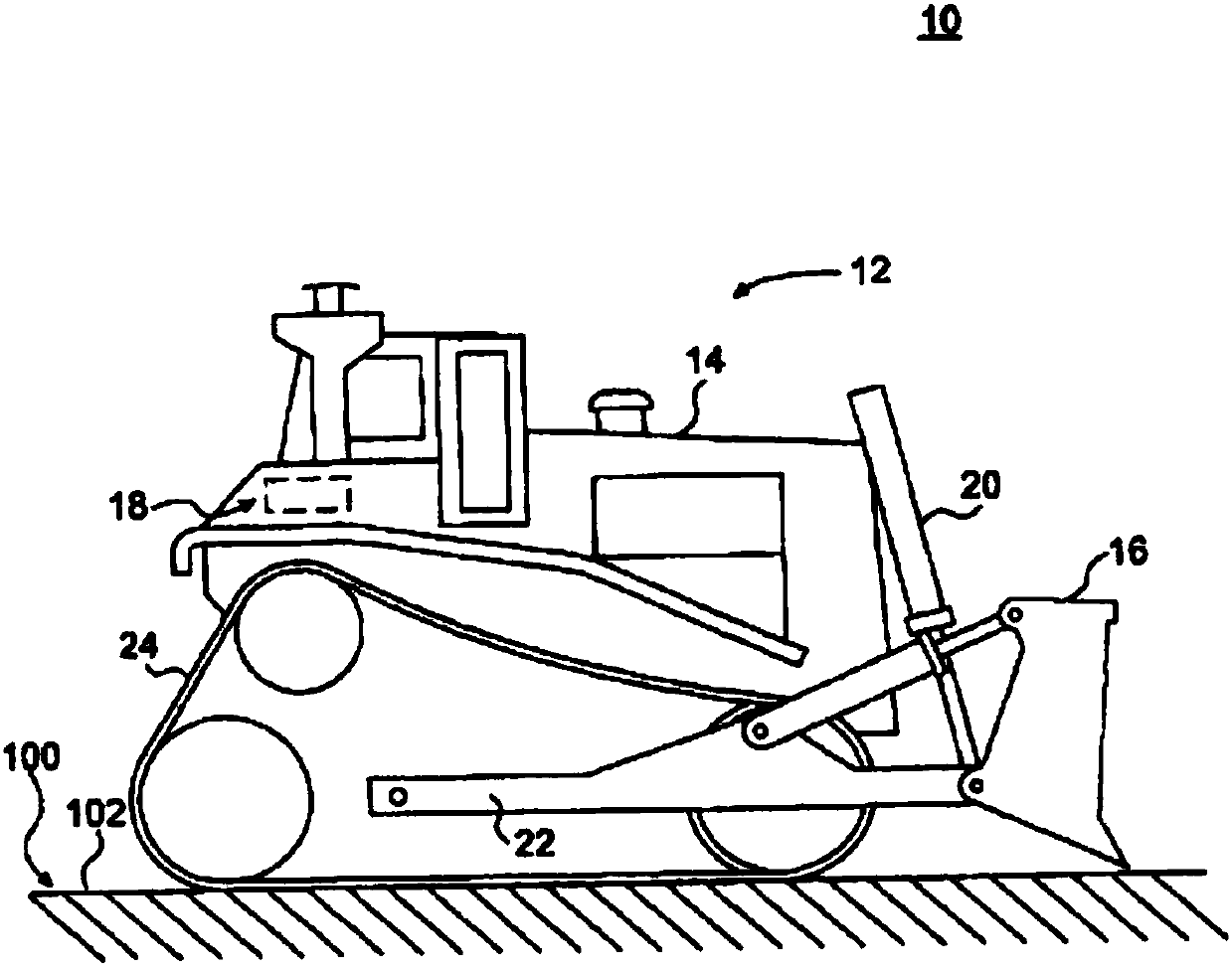
[0009] figure 1 An exemplary civil engineering machine 12 is shown. Civil engineering machine 12 may be a mobile machine that performs work related to some industry, such as mining, construction, farming, or other industries known in the art. For example, civil engineering machine 12 may be a bulldozer, loader, backhoe, excavator, motor grader, or any other civil engineering machine known in the art. Civil engineering machine 12 may be configured to traverse...


PUM


Abstract

The invention discloses a system for controlling a civil engineering tool. The method comprises the following steps: at least partially determining first cutting depth of the civil engineering tool based on ability of the civil engineering tool; at least partially determining second cutting depth of the civil engineering tool according to expected slope of a construction site (10); and moving thecivil engineering tool by responding to at least one of the first cutting depth and the second cutting depth.

Description

technical field [0001] The present invention relates to a system for controlling a civil engineering tool, and more particularly to a method and apparatus for controlling a civil engineering tool relative to the working depth of a cut. Background technique [0002] Civil engineering machines such as bulldozers, loaders, excavators, motor graders, and other types of earth moving machines are commonly used to remove material from a worksite to achieve a desired grade of the worksite. In particular, it may be desirable to remove a first layer of material, thereby exposing a second material underlying the first layer. For example, it may be desirable to remove layers of soil and / or rock to expose valuable carbon or other ore layers. In addition, it may be desirable to remove layers of material to achieve a desired slope, thereby preparing the site for further construction. For example, it may be desirable to remove layers of dirt and / or rock to create a desired slope for a par...

Claims


Application Information

Patent Timeline
IPC IPC(8): E02F9/20
Inventor 薛思源张利董方圆
Owner 薛思源
Why Eureka
Try Eureka