
Switching circuit and control method for short-circuiting mode of electronic load

A technology of electronic load and switching circuit, which is applied in the field of switching circuit and control of electronic load short-circuit mode, which can solve the problems of easy triggering of electronic load protection mechanism and failure of electronic load short-circuit mode, and achieve the effect of reducing failure

Active Publication Date: 2019-06-25
SHENZHEN CITY SIGLENT TECH
View PDF5 Cites 0 Cited by
  • Summary
  • Abstract
  • Description
  • Claims
  • Application Information

AI Technical Summary

Problems solved by technology

[0004] The technical problem mainly solved by the present invention is that when the electronic load enters the short-circuit mode, it is easy to trigger the electronic load protection mechanism, resulting in the technical problem that the electronic load short-circuit mode does not take effect

Method used


Image

  • Switching circuit and control method for short-circuiting mode of electronic load
  • Switching circuit and control method for short-circuiting mode of electronic load
  • Switching circuit and control method for short-circuiting mode of electronic load

Examples


Embodiment 1

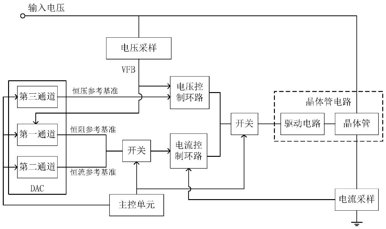
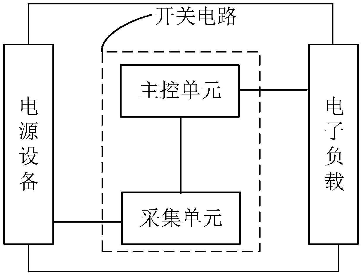
[0029] Such as image 3 As shown, it is a schematic structural diagram of a switching circuit of an embodiment, which is connected between the power supply device and the electronic load, and is used to control the working mode of the electronic load, including an acquisition unit and a main control unit. The acquisition unit is used to acquire the voltage value of the power supply equipment connected to the electronic load in real time. The main control unit is connected with the electronic load, and is used for comparing the voltage value collected in real time with a preset value in response to the instruction of the electronic load switching to the short-circuit mode, so as to obtain a comparison result. According to the comparison result, the electronic load is switched to short circuit mode. Specifically, when the comparison result is that the voltage value is less than the preset value, the main control unit switches the electronic load to the short-circuit mode; when ...

Embodiment 2

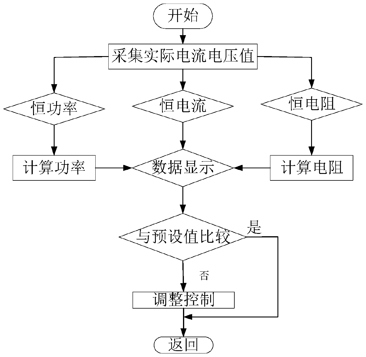
[0033] In the embodiment of the present application, a control method for the switching circuit in the short-circuit mode of the electronic load is also disclosed, such as Figure 4 As shown, it is a flowchart of an electronic switch control method in an embodiment, including:

[0034] 1) Real-time acquisition of the voltage value of the power supply equipment connected to the electronic load;

[0035]Connect the electronic load to the power supply, and set the voltage and current of the power supply. For example, set the voltage of the power supply to 70V and the current to 2A, which should meet the operating parameters of the electronic load, and the electronic load will output in constant current mode. Then set the short-circuit mode of the electronic load, turn on the power supply device and the electronic load, and collect the instantaneous voltage value of the power supply device.

[0036] 2) In response to an instruction to switch the electronic load to a short-circui...


PUM


Abstract

The present application discloses a switching circuit and control method for the short-circuiting mode of an electronic load and belongs to the technical field of test measurement. Before the workingmode of the electronic load is converted to the short-circuit mode, the voltage value of a power source collecting device is compared with a preset value, so that a comparison result is obtained; andthe electronic load is controlled to be switched to the short-circuit mode according to the comparison result, so that the current of the electronic load does not tend to oscillate; the possibility ofthe triggering of an electronic load protection mechanism is low, so that the electronic load does not tend to be turned off due to the triggering of the electronic load protection mechanism, and therefore, the failure of the short-circuiting mode of the electronic load can be decreased.

Description

technical field [0001] The invention relates to the technical field of test and measurement, in particular to a switch circuit and a control method for electronic load short-circuit mode. Background technique [0002] In the fields of electronics, communication, and energy, it is necessary to perform power output tests on power supply equipment such as power regulators, batteries, and power electronic components. Electronic load is a commonly used test and measurement equipment. It uses the combined functions of various circuits to simulate electrical equipment or loads in real environments, and is used to test and evaluate power output equipment such as chargers and batteries. The emergence of programmable DC electronic loads combines computer control technology with the functions of traditional electronic loads, which can provide load functions of various properties and parameters, and has incomparable advantages over simple resistive loads. It has been widely used in pra...

Claims


Application Information

Patent Timeline
IPC IPC(8): G01R31/40G01R1/04G01R1/20
Inventor 谢林冬周云海谢炳涛
Owner SHENZHEN CITY SIGLENT TECH
Learn More