Film coating tool
A jig and jig board technology, applied in the direction of optical components, optics, instruments, etc., can solve the problems of low utilization rate and narrow use range of coating jigs, and achieve the effect of solving the narrow use range and widening the use range
- Summary
- Abstract
- Description
- Claims
- Application Information
AI Technical Summary
Problems solved by technology
Method used
Image

Examples
Embodiment 1
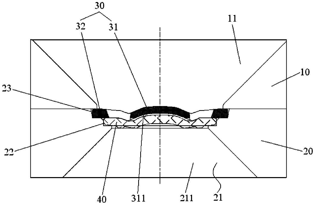
[0027] Such as figure 1 As shown, the coating jig includes an upper jig plate 10 , a lower jig plate 20 and a shield 30 . Wherein, the upper jig plate 10 has a first lens plated hole 11 . The lower jig plate 20 has a second lens plated hole 21, the upper jig plate 10 is detachably arranged on the lower jig plate 20, the first lens plated hole 11 communicates with the second lens plated hole 21, and the film to be coated The lens 40 is placed in the second lens plated hole 21 . The blocking member 30 is interposed between the upper jig plate 10 and the lower jig plate 20 and is located directly above the lens 40 to be coated.
[0028] Applying the technical solution of this embodiment, the blocking member 30 is sandwiched between the upper jig plate 10 and the lower jig plate 20 and is located directly above the lens 40 to be coated, so as to absorb the non-effective diameter area of the lens 40 to be coated. of plating. In this way, there is no mutual connection relation...
Embodiment 2
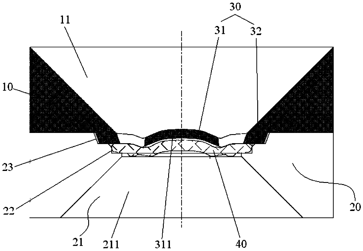
[0050] The difference between the coating jig in the second embodiment and the first embodiment is that the shielding member 30 and the upper jig plate 10 are integrally formed.
[0051] Such as image 3 As shown, the shielding member 30 and the upper jig plate 10 are integrally formed to simplify the overall structure of the coating jig, further reduce the coating process, and save time and manufacturing costs.
[0052] Optionally, the shielding member 30 and the upper jig plate 10 are formed by injection molding or stamping. The above-mentioned processing method is relatively simple, reduces the processing cost of the coating jig, and shortens the processing time.
Embodiment 3
[0054] The difference between the coating fixture in the third embodiment and the first embodiment lies in that the structure of the mounting part 32 is different.
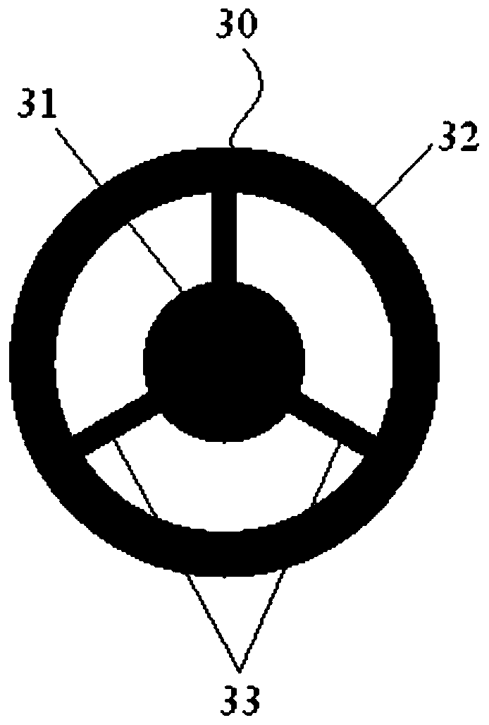
[0055] Optionally, the installation part includes a plurality of installation pieces and a plurality of connecting ribs, the plurality of connection ribs are arranged at intervals along the circumference of the shielding part, the installation pieces and the shielding parts are respectively connected to both ends of the connecting ribs, and the installation pieces are sandwiched between Between the upper fixture plate and the lower fixture plate. In this embodiment, the mounting part includes three mounting pieces and three connecting ribs, the three mounting pieces are provided in one-to-one correspondence with the three connecting ribs, and the mounting pieces and the shielding parts are respectively connected to two ends of the corresponding connecting ribs. Wherein, the thickness of the connecting ribs is as s...
PUM
 Abstract
Description
Claims
Application Information
 - R&D Engineer
- R&D Manager
- IP Professional
- Industry Leading Data Capabilities
- Powerful AI technology
- Patent DNA Extraction
Browse by: Latest US Patents, China's latest patents, Technical Efficacy Thesaurus, Application Domain, Technology Topic.
© 2024 PatSnap. All rights reserved.Legal|Privacy policy|Modern Slavery Act Transparency Statement|Sitemap