Communication equipment protection device

A technology for protection devices and communication equipment, applied in the direction of cooling/ventilation/heating transformation, etc., can solve problems such as poor construction performance, large size and weight of communication equipment, reduce damage, reduce construction difficulty, and improve heat dissipation efficiency Effect

Inactive Publication Date: 2019-06-25
滑迪
View PDF1 Cites 2 Cited by
  • Summary
  • Abstract
  • Description
  • Claims
  • Application Information

AI Technical Summary

Problems solved by technology

[0002] Existing communication equipment such as couplers, starter cabinets, etc., are used in distribution systems, repeaters or other application fields, and are installed indoors or outdoors by hanging and fixing, and realize their respective functions while connecting with communication cables. However, when the existing communication equipment is connected to the communication cable, due to the large size and weight of the communication equipment, the joints and the communication equipment themselves generally do not adopt dustproof or waterproof, anti-sunshine and other related protection measures, even if relevant measures are adopted , and only in the protection of the butt joints, for this reason we propose a protection device for communication equipment, which makes it easy to install and disassemble, and has good sealing performance
[0003] After searching, the Chinese patent authorization number is CN 206596313U, which discloses a protection device for communication equipment, including a fixed plate. The top of the fixed plate is provided with a vertically arranged fixed ring, and the outside of the fixed ring is provided with a first Groove, the first groove is located on the fixing plate, the cross section of the first groove and the fixing ring is rectangular, but the sealing of this device is too good, resulting in poor ventilation and heat dissipation, and it is not conducive to lifting and installation, and the construction performance is poor

Method used


Image

  • Communication equipment protection device
  • Communication equipment protection device

Examples


Embodiment Construction

[0020] The following will clearly and completely describe the technical solutions in the embodiments of the present invention with reference to the accompanying drawings in the embodiments of the present invention. Obviously, the described embodiments are only some, not all, embodiments of the present invention.

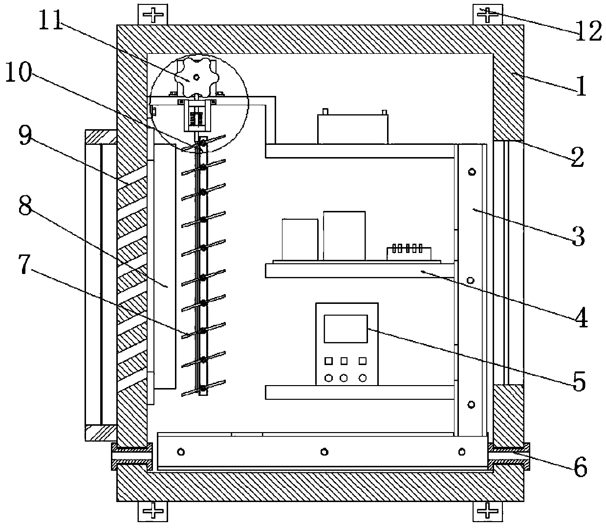
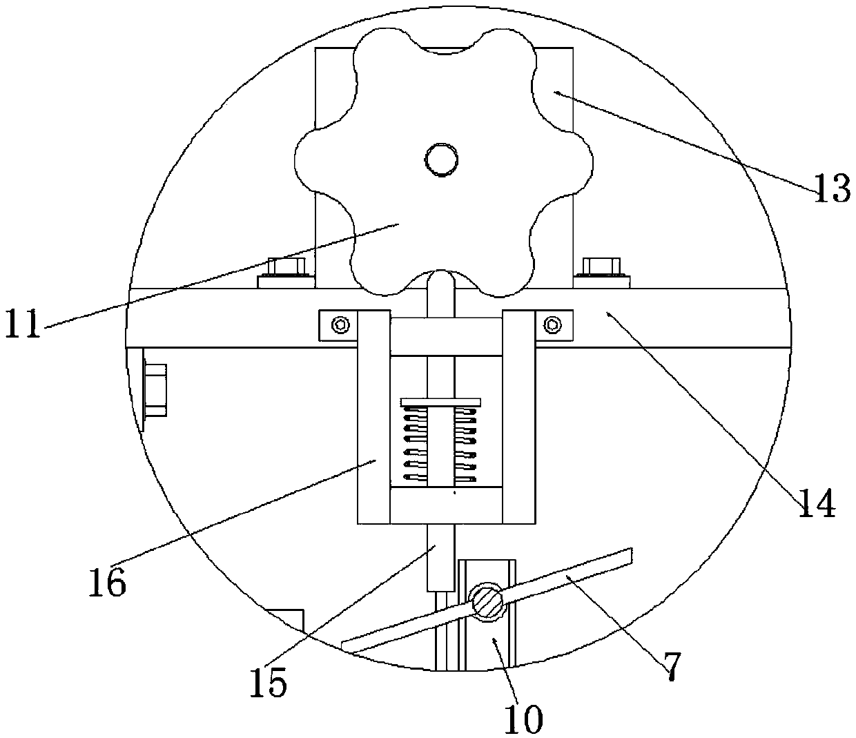
[0021] refer to Figure 1-2 , a communication equipment protection device, including a box body 1, three parallel mounting plates 4 are welded on the inner wall of the back of the box body 1, and the upper surface of the topmost mounting plate 4 and the inner wall of the box body 1 are fixed by bolts A crossbeam 14, and the upper surface of the crossbeam 14 is fixed with a motor 13 by bolts, the top of the output shaft of the motor 13 is keyed to a cam 11, and the side of the crossbeam 14 near the cam 11 is fixed with a sliding frame by bolts, and the sliding frame is connected with a The ejector rod 15, the outer walls on both sides of the box body 1 are respectivel...


PUM


Abstract

The invention discloses a communication equipment protection device, which comprises a box body. Three parallel mounting plates are welded to the back inner wall of the box body. A cross beam is fixedbetween the upper surface of the mounting plate at the top and the inner wall of the box body through bolts, and a motor is fixed on the upper surface of the cross beam through bolts. The top end ofthe output shaft of the motor is in key joint with a cam. A sliding frame is fixed by bolts to one side of the cross beam near the cam, and an ejector rod is connected in a sliding manner in the sliding frame. Through holes and equally-spaced inclined holes are formed in the outer walls of two opposite sides of the box body. A radiating fan is fixed by bolts on the inner wall of one side of the box body near the inclined holes. Cooling and heat dissipation are realized at any corner of the box body. The box body can be horizontally fixed at an installation position more easily and can be hoisted more easily, and the construction difficulty is reduced. Moreover, the radiating efficiency is improved, the energy consumption is reduced, and the device is made more environment-friendly.

Description

technical field [0001] The present invention relates to the technical field of communication equipment, in particular to a protection device for communication equipment. Background technique [0002] Existing communication equipment such as couplers, starter cabinets, etc., are used in distribution systems, repeaters or other application fields, and are installed indoors or outdoors by hanging and fixing, and realize their respective functions while connecting with communication cables. However, when the existing communication equipment is connected to the communication cable, due to the large size and weight of the communication equipment, the joints and the communication equipment themselves generally do not adopt dustproof or waterproof, anti-sunshine and other related protection measures, even if relevant measures are adopted , and only in the protection of the butt joint, we propose a protection device for communication equipment, which makes it easy to install and disa...

Claims


Application Information

Patent Timeline
Patent Type & Authority Applications(China)
IPC IPC(8): H05K7/20
Inventor 滑迪
Owner 滑迪
Why Eureka
Try Eureka