High-precision film laminating system

A high-precision, lamination technology, applied in the direction of layered products, lamination auxiliary operations, lamination, etc., can solve the problems of increased defective products, incomplete lamination, incomplete lamination, etc., to improve lamination accuracy , Improve the coating yield and ensure the effect of product quality

Active Publication Date: 2019-06-28
苏州凌文机电科技有限公司
View PDF5 Cites 1 Cited by
  • Summary
  • Abstract
  • Description
  • Claims
  • Application Information

AI Technical Summary

Problems solved by technology

[0002] In the laminating machine in the prior art, the material is loaded manually or through the conveyor belt. This feeding method has poor positioning accuracy, which will cause the material to deviate and fail to be completely coated, and the material is easily separated from the conveyor belt bracket. Sliding occurs, and uniform feeding cannot be maintained, resulting in uneven coating. Manual feeding requires workers to continuously push materials according to the coating situation, which consumes energy and accuracy cannot be guaranteed; after the coating is completed, the protective film is directly cut by the moving cutter Cutting, the protective film will be lifted up during the cutting process of this film cutting method, so that the film covering of the product is not complete, and it will also cause air to enter, and the film covering effect is poor, resulting in defective products and scrapping; the film laminating machine is feeding materials After the film is finished, the material is transported out through the conveyor belt, and it is manually removed and stacked next to the conveyor belt, which consumes manpower and is inefficient, and it is easy to cause wear and tear on the material coating and increase the generation of defective products.

Method used


Image

  • High-precision film laminating system
  • High-precision film laminating system
  • High-precision film laminating system

Examples


Embodiment Construction

[0029] The specific embodiments of the present invention will be further described below in conjunction with the accompanying drawings and examples. The following examples are used to describe the technical solution of the present invention more clearly, but not to limit the protection scope of the present invention.

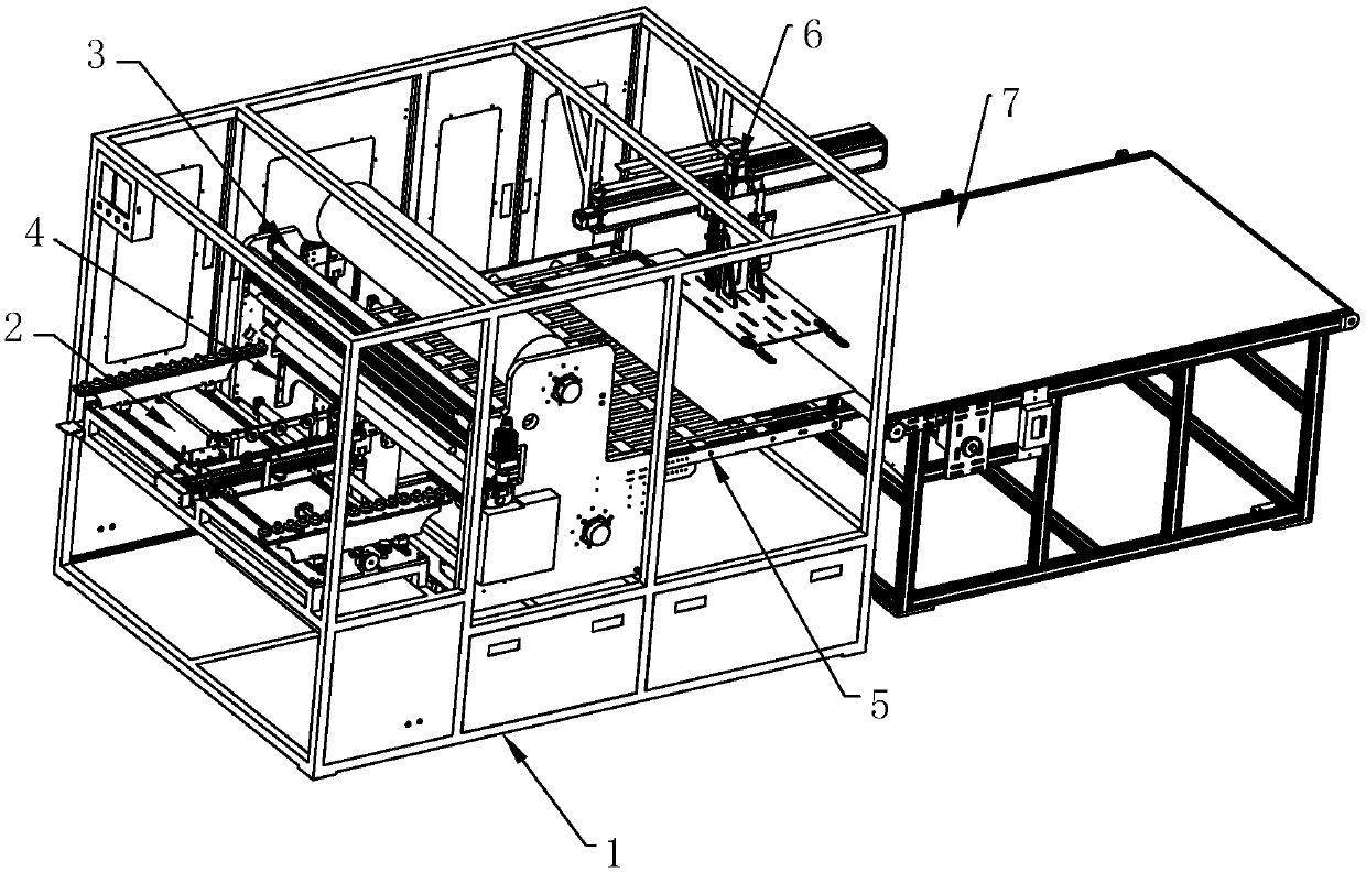
[0030] Such as figure 1 The high-precision film coating system shown includes a frame body 1, and the frame body 1 is sequentially provided with a feeding mechanism 2, a film covering mechanism 3, a film cutting mechanism 4, a discharge conveyor belt 5, and a blanking mechanism 6, and the blanking mechanism One end of 6 is provided with code material conveyor belt 7.

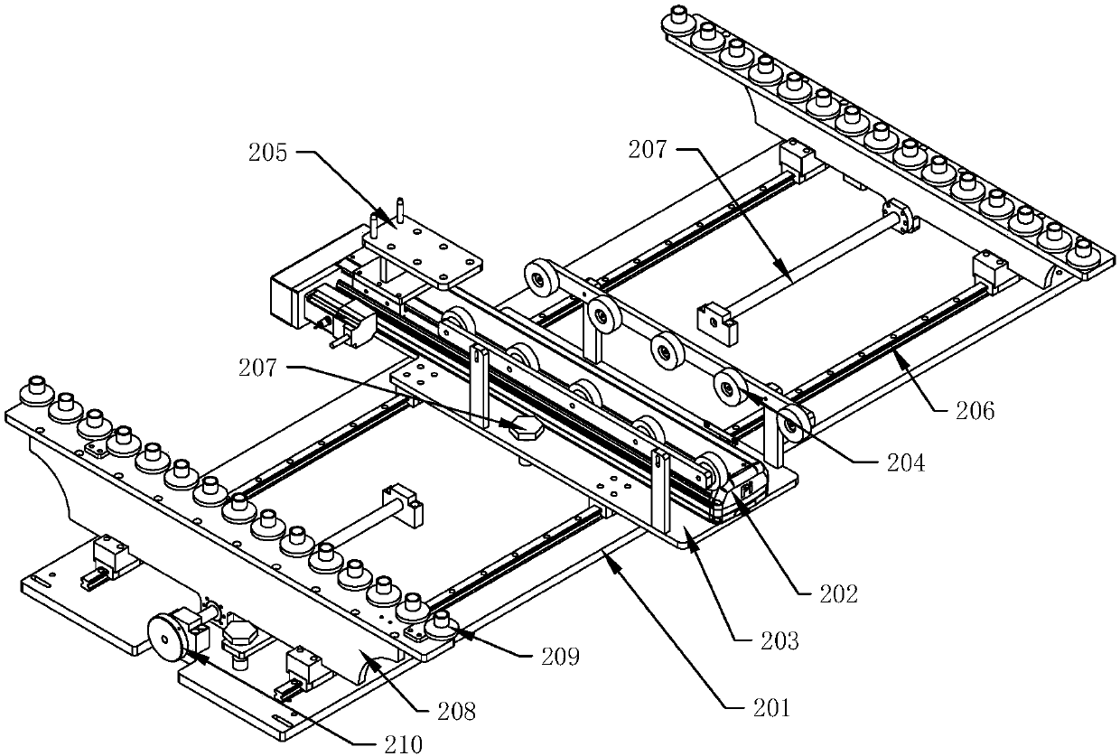
[0031] Such as figure 2 As shown, the feeding mechanism 2 includes a feeding base plate 201, the feeding base plate 201 is fixed on the frame body 1, and the top of the feeding base plate 201 is symmetrically fixed with two adjusting slide rails 206 by bolts, and the adjusting slide rails 206 T...


PUM


Abstract

The invention relates to a high-precision film laminating system. The high-precision film laminating system comprises a frame body, wherein a loading mechanism, a film laminating mechanism, a film cutting mechanism, a discharging conveying belt and an unloading mechanism are sequentially arranged in the frame body, and a stacked material conveying belt is arranged at one end part of the unloadingmechanism; the loading mechanism comprises a loading base plate, an adjusting sliding rail is arranged at the top of the loading base plate, a loading support plate is arranged in the middle of the adjusting sliding rail, positioning brackets are arranged on two sides of the loading support plate, and the loading support plate and the positioning bracket are connected with the adjusting sliding rail in a sliding manner; positioning bolts and a linear sliding table are arranged on the loading support plate, loading pulley blocks are arranged on the loading support plate on two sides of the linear sliding table, and a material pushing claw is arranged on a sliding block of the linear sliding table; and positioning rollers are uniformly arranged at the tops of the positioning brackets, the bottoms of the positioning brackets are cooperatively connected with an adjusting lead screw at the top of the loading base plate, and an adjusting rotating disc is arranged at the end part of the adjusting lead screw.

Description

technical field [0001] The invention belongs to the technical field of film covering, and in particular relates to a high-precision film covering system. Background technique [0002] In the laminating machine in the prior art, the material is loaded manually or through the conveyor belt. This feeding method has poor positioning accuracy, which will cause the material to deviate and fail to be completely coated, and the material is easily separated from the conveyor belt bracket. Sliding occurs, and uniform feeding cannot be maintained, resulting in uneven coating. Manual feeding requires workers to continuously push materials according to the coating situation, which consumes energy and accuracy cannot be guaranteed; after the coating is completed, the protective film is directly cut by the moving cutter Cutting, the protective film will be lifted up during the cutting process of this film cutting method, so that the film covering of the product is not complete, and it will...

Claims


Application Information

Patent Timeline
Patent Type & Authority Applications(China)
IPC IPC(8): B32B38/10B32B38/00
Inventor 赫英楠
Owner 苏州凌文机电科技有限公司
Why Eureka
Try Eureka