Automatic lubricating equipment for textile yarns

An automatic lubricating and spinning yarn technology, applied in the direction of conveying filamentous materials, thin material processing, transportation and packaging, etc., can solve the problems of workers cleaning troubles, lubricating oil waste, and oil flow adjustment, etc., to achieve convenience High-precision adjustment, high transmission precision, and the effect of avoiding condensation

Active Publication Date: 2019-06-28
扬州金晟华线业有限公司
View PDF11 Cites 9 Cited by
  • Summary
  • Abstract
  • Description
  • Claims
  • Application Information

AI Technical Summary

Problems solved by technology

[0002] In the textile industry, there are many equipments that use a variety of yarns. If the yarns used in the existing knitting machines are not lubricated before weaving, the yarns are likely to rub against the equipment during the weaving process, causing damage. The fibers on the surface of the yarn cause wear and tear, resulting in a large amount of hairiness to form flying flowers, which will not only pollute the workshop, cause various diseases, but also cause fire hazards
In order to reduce the resistance caused by the yarn during the sewing process, and also to ensure smooth weaving, the yarn is often soaked with oil before working. At present, the existing lubricating device cannot properly adjust the oil flow, so that different thicknesses The yarn cannot be lubricated by suitable lubricating oil, resulting in a waste of lubricating oil. At the same time, there is too much lubricating oil after the yarn is lubricated, so that the lubricating oil drips on the ground, which brings great trouble to the cleaning of workers.

Method used

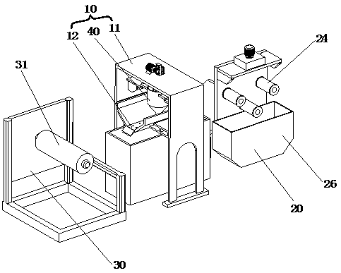
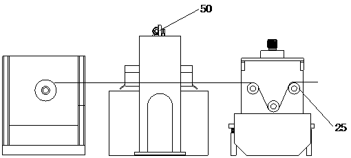
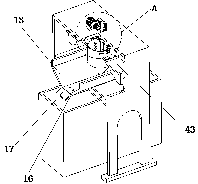

Image

  • Automatic lubricating equipment for textile yarns
  • Automatic lubricating equipment for textile yarns
  • Automatic lubricating equipment for textile yarns

Examples


Embodiment Construction

[0026] The technical solutions of the present invention will be clearly and completely described below in conjunction with the accompanying drawings. Apparently, the described embodiments are some of the embodiments of the present invention, but not all of them.

[0027] In the description of the present invention, it should be noted that the terms "center", "upper", "lower", "left", "right", "vertical", "horizontal", "inner", "outer" etc. The indicated orientation or positional relationship is based on the orientation or positional relationship shown in the drawings, and is only for the convenience of describing the present invention and simplifying the description, rather than indicating or implying that the referred device or element must have a specific orientation, or in a specific orientation. construction and operation, therefore, should not be construed as limiting the invention. In addition, the terms "first", "second", and "third" are used for descriptive purposes on...


PUM


Abstract

The invention discloses automatic lubricating equipment for textile yarns, and belongs to the technical field of textile equipment. The equipment comprises a lubricating assembly, a residual liquid removing assembly and a bearing frame, an upper winding roller is arranged on the bearing frame, the lubricating assembly comprises an oil outlet component, a gantry frame and a bearing platform, the oil outlet component comprises a heating cylinder, a buffer part, an oil outlet hopper, a limiting disc and a lifting part, the oil outlet hopper communicates with the interior of the heating cylinder,the bottom of the oil outlet hopper is provided with an oil outlet hole, and the bottom of the limiting disc is provided with a curve chamfer. Lubricating operation for the yarns can be achieved through the lubricating assembly, residual lubricating oil stuck on the yarns can be removed through the residual liquid removing assembly, lubricating oil can be vibrated through a vibration component, anair blower can be matched with the vibration component, and lubricating oil stuck on the yarns can fall down to an oil storage tank.

Description

technical field [0001] The invention relates to the technical field of textile equipment, in particular to automatic lubrication equipment for textile yarns. Background technique [0002] In the textile industry, there are many equipments that use a variety of yarns. If the yarns used in the existing knitting machines are not lubricated before weaving, the yarns are likely to rub against the equipment during the weaving process, causing damage. The fibers on the surface of the yarn cause wear and tear, resulting in a large amount of hairiness to form flying flowers, which will not only pollute the workshop, cause various diseases, but also cause fire hazards. In order to reduce the resistance caused by the yarn during the sewing process, and also to ensure smooth weaving, the yarn is often soaked with oil before working. At present, the existing lubricating device cannot properly adjust the oil flow, so that different thicknesses The yarn cannot be lubricated by suitable lu...

Claims


Application Information

Patent Timeline
Patent Type & Authority Applications(China)
IPC IPC(8): B65H71/00B65H54/547
Inventor 蒋雨航
Owner 扬州金晟华线业有限公司
Why Eureka
Try Eureka