

Fuel injection valve
A fuel injection valve, fuel technology, applied in the direction of fuel injection devices, special fuel injection devices, fuel injection devices with anti-corrosion measures, etc.
- Summary
- Abstract
- Description
- Claims
- Application Information
AI Technical Summary
Problems solved by technology
Method used
Image

Examples
no. 1 example
[0020] A fuel injection valve of a first embodiment of the present disclosure injects fuel for combustion of an internal combustion engine from an injection hole. The internal combustion engine is a compression ignition diesel engine, and is installed in a vehicle as a driving source for travel. Fuel (such as light oil) remaining in a fuel tank not shown is pressure-delivered into the common rail by a high-pressure fuel pump, and then distributed from the common rail into each fuel injection valve 10 and injected from the fuel injection valve 10 to the combustion in the room.
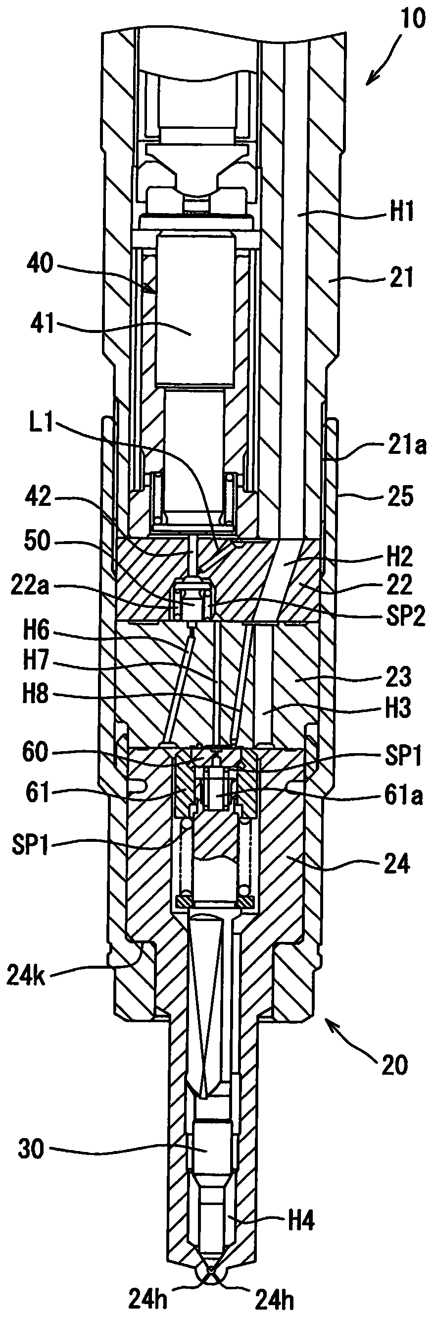
[0021] Such as figure 1 As shown, the fuel injection valve 10 includes a body 20 , a valve needle 30 , a driving part 40 , a control valve element 50 , a control plate 60 and a cylinder 61 .
[0022] The body 20 includes a plurality of metal parts, such as a driving part body 21 , a valve plate 22 , an orifice plate 23 , and a valve body 24 , which are combined together by holding nuts 25 . Specifica...
no. 2 example
[0048] Such as Figure 6 As shown, the valve body 24A of the second embodiment has an intermediate layer 244 positioned between a sacrificial corrosion layer 245 and a corrosion resistant layer 242 . The intermediate layer 244 is provided by stacking a plurality of films. exist Figure 6 In , the respective films are indicated as intermediate layers 244a, 244b and 244c.
[0049] Each of the intermediate layers 244a, 244b, and 244c is formed by a method of depositing a film on the surface of the sacrificial etching layer 245 by chemical reaction in the gas phase, that is, by a chemical vapor deposition process. In particular, intermediate layers 244a, 244b, and 244c are desirably formed by atomic layer deposition (ALD), which is a chemical vapor deposition process.
[0050] The intermediate layer 244 has a linear expansion coefficient lower than that of one of the sacrificial corrosion layer 245 and the corrosion-resistant layer 242 and higher than that of the other of the s...
no. 3 example
[0061] Such as Figure 4 As shown, the valve body 24 of the first embodiment has a structure in which a sacrificial corrosion layer 245 and a corrosion-resistant layer 242 are disposed on a base material 241 . On the other hand, if Figure 7 As shown, the valve body 24B of the third embodiment has a structure in which a diffusion preventing layer 243 is provided on a base material 241 in addition to a sacrificial corrosion layer 245 and a corrosion-resistant layer 242 . The diffusion preventing layer 243 will now be described in detail.
[0062] The diffusion barrier layer 243 is located between the base material 241 and the sacrificial corrosion layer 245, and is made of, for example, aluminum oxide (Al 2 o 3 ) in which diffusion of the metal component (for example, iron) of the base material 241 is less likely to occur than in the corrosion-resistant layer 242 and the sacrificial corrosion layer 245. While "diffusion" is known as the phenomenon in which matter is dispers...
PUM
 Abstract
Description
Claims
Application Information