Peristaltic pump head

A peristaltic pump and pump head technology, applied in the field of pump components, can solve the problems of manual removal of the pressure tube card, laborious disassembly and assembly, low work efficiency, etc., and achieve faster and more labor-saving disassembly and assembly, wide applicability, and labor-saving disassembly and assembly. Effect

Pending Publication Date: 2019-06-28
CHANGZHOU PREFLUID TECH
View PDF0 Cites 3 Cited by
  • Summary
  • Abstract
  • Description
  • Claims
  • Application Information

AI Technical Summary

Problems solved by technology

[0003] The technical problem to be solved by the present invention is: in order to solve the technical problems that the pump head of the peristaltic pump in the prior art needs to manually remove the pressure tube card, the disassembly and assembly are laborious, and the work efficiency is low, the present invention provides a peristaltic pump pump head to solve the above problems

Method used


Image

  • Peristaltic pump head
  • Peristaltic pump head
  • Peristaltic pump head

Examples


Embodiment 1

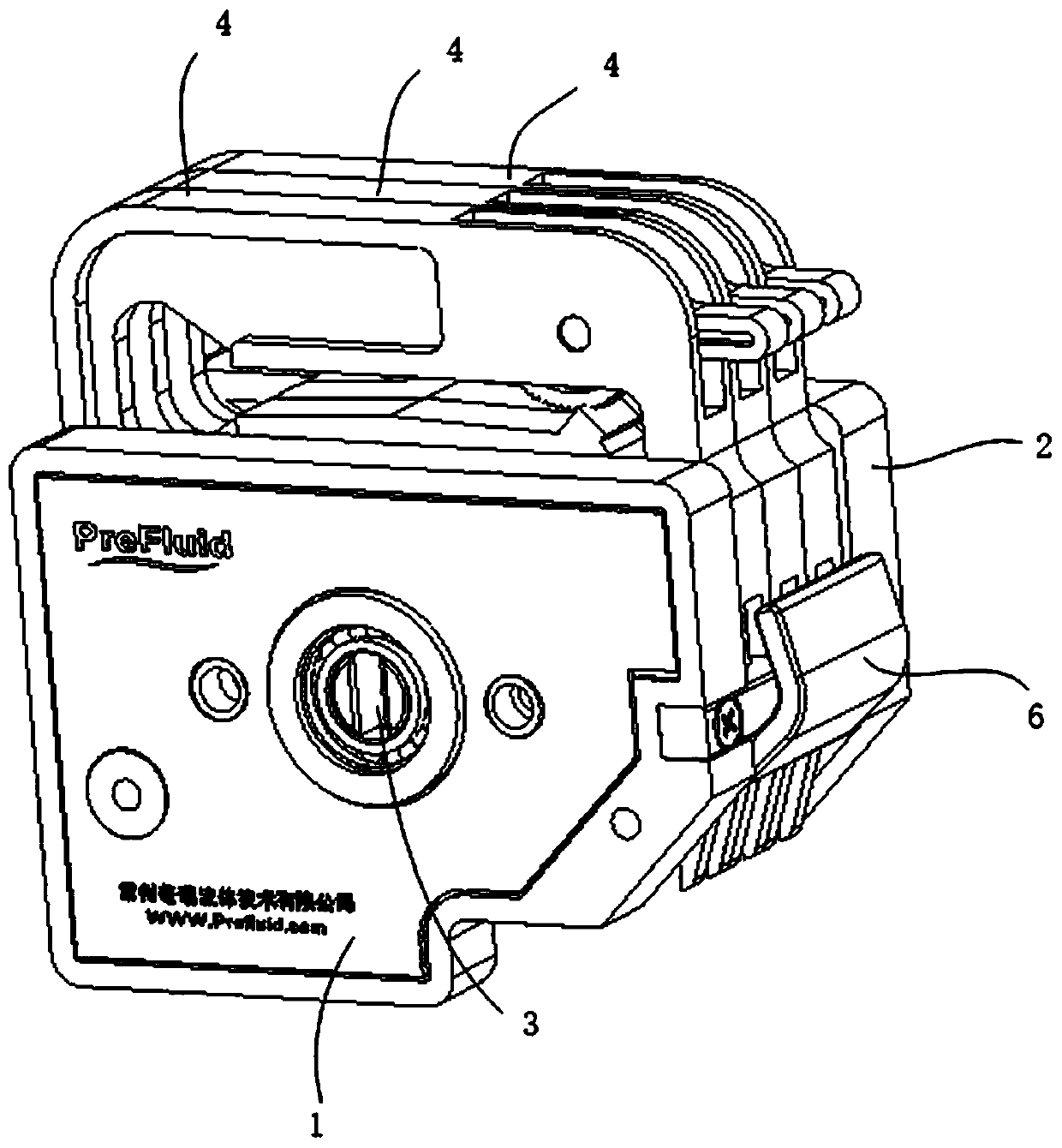
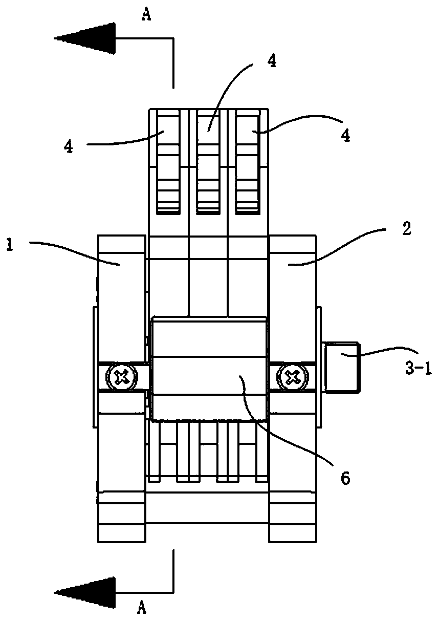
[0035] Example 1, such as Figure 1-Figure 3 As shown, a peristaltic pump head includes a front baffle 1, a rear baffle 2 and a roller assembly 3, the front and rear ends of the roller assembly 3 are respectively rotatably connected to the front baffle 1 and the rear baffle 2, and the roller assembly 3 includes The rotating shaft 3-1 and the roller group sleeved on the rotating shaft 3-1, the roller group includes a roller bracket 3-2 and a roller 3-3, and the roller bracket 3-2 is arranged in a circular array with the rotating shaft 3-1 as the center There are a plurality of mandrels 3-4, and each mandrel 3-4 is sleeved with a roller 3-3. There are three pressure tube cards 4 between the front baffle 1 and the rear baffle 2. The pressure tube cards 4 include a fixed part 4-2 and a pressure tube part 4-1. The elastic hose is located between the pressure tube part 4-1 and the roller. Between 3-3, fixed side arms are arranged on both sides of the fixed part 4-2, which is a door...

Embodiment 2

[0038] Embodiment 2, on the basis of Embodiment 1, the side of the fixed side arm in contact with the wrench 6 is an inclined plane, and the inclined plane gradually inclines to the inner side of the fixed part 4-2 from top to bottom; when the fixed side arm is clamped When on the support column 5, the upper surface of one end of the wrench 6 is pressed into contact with the inclined plane, and the other end of the wrench 6 is against the support column 5 (such as Figure 4 As shown), that is, the wrench 6 is set on the top to prevent the wrench 6 from occupying the connection space of the protruding elastic hose; when the wrench 6 is rotated downward, the fixed side arm is separated from the support column 5, and the end of the wrench 6 close to the fixed side arm The upper part is a raised arc-shaped structure, and the upper surface of the end of the wrench 6 is a plane, and the distance from the outer edge of the raised arc-shaped structure to the wrench pin 7 is greater tha...

Embodiment 3

[0039] Example 3, such as Image 6 with Figure 7 As shown, on the basis of Embodiment 1 or Embodiment 2, the pressure tube card 4 also includes a ratchet 4-3, and the outer ring of the ratchet 4-3 is provided with a ratchet 4-31; the ratchet 4-31 of the ratchet 4-3 Usually one-way teeth (such as Figure 9 Shown in the enlarged area), it is more labor-saving to turn the ratchet 4-3 when pressing the pressing tube part 4-1. The ratchet 4-3 is movably connected with the fixed part 4-2, one end of the pressure tube part 4-1 is a fixed end, and the other end is a movable end, the fixed end is fixed with the fixed part 4-2, and the movable end is connected with the ratchet 4 -31 fit, the pressure tube part 4-1 is located inside the fixed part 4-2, and the lower surface of the pressure tube part 4-1 is a concave arc-shaped surface, corresponding to the arc-shaped upper surface structure of the roller assembly 3 . The ratchet 4-3 is located above the pressing tube part 4-1, and c...


PUM


Abstract

The invention discloses a peristaltic pump head. The pump head comprises a front baffle, a rear baffle and a roller component, the front end and the rear end of the roller component are rotationally connected with the front baffle and the rear baffle respectively, one or more pipe pressing cards are arranged between the front baffle and the rear baffle, the pipe pressing piece comprises a fixing part and a pipe pressing part, the elastic hose is located between the pipe pressing part and the roller component, a fixed side arm is arranged on the two sides of the fixed part, two supporting columns are arranged between the front baffle and the rear baffle, the fixed side arms on the two sides are clamped on the two supporting columns respectively, and a spanner used for opening the fixed sidearm is further arranged between the front baffle and the rear baffle. The elastic hose is limited in the peristaltic pump through the pipe pressing clamping piece, the pressing pipe clamping piece isclamped and fixed with the front baffle and the rear baffle, no redundant detachable parts are arranged, when the number of the pipe pressing clamping pieces is large, the fixing side arm of each pressing pipe clamping piece can be pried by a spanner at one time, and the disassembling and assembling are more rapid and more labor-saving.

Description

technical field [0001] The invention relates to a pump component, in particular to a pump head of a peristaltic pump. Background technique [0002] Peristaltic pump is a kind of positive displacement pump, which is mainly used for the distribution and transportation of fluid. When the pump head of the peristaltic pump is working, the roller rotates, squeezes the elastic hose, and transports the fluid through the elastic hose. In the peristaltic pump structure with only the front baffle and the rear baffle, it is necessary to use the pressure tube card to squeeze the elastic hose , the pressure tube card is made of plastic material, has a certain toughness, and can be fixed with the front baffle and the rear baffle. Usually, when disassembling the pressure tube card, you only need to directly open the clamping part of the pressure tube card, but When the number of pressure tube cards is large, it will be very difficult to open the card setting parts at one time, and the pres...

Claims


Application Information

Patent Timeline
Patent Type & Authority Applications(China)
IPC IPC(8): F04B43/12F04B53/22
Inventor 储江波
Owner CHANGZHOU PREFLUID TECH
Why Eureka
Try Eureka