Self-positioning resistance repairing fixture

A self-positioning and resistance repairing technology, applied in resistors, resistance manufacturing, liquid/fluid solid measurement, etc., can solve the problems of path deviation, high product scrap rate, large positioning error, etc.

Active Publication Date: 2019-06-28
广德方晟科技有限公司
View PDF4 Cites 0 Cited by
  • Summary
  • Abstract
  • Description
  • Claims
  • Application Information

AI Technical Summary

Problems solved by technology

[0004] Aiming at the deficiencies of the prior art, the present invention provides a self-positioning and repairing jig, which has the advantages that when one side of the chip is adjusted, the other side can automatically adjust its position according to the change, etc., which solves the problem of product positioning during repositioning. If the error is too large, path deviation will occur during laser repair, resulting in a high product scrap rate

Method used


Image

  • Self-positioning resistance repairing fixture
  • Self-positioning resistance repairing fixture

Examples


Embodiment Construction

[0017] The following will clearly and completely describe the technical solutions in the embodiments of the present invention with reference to the drawings in the embodiments of the present invention.

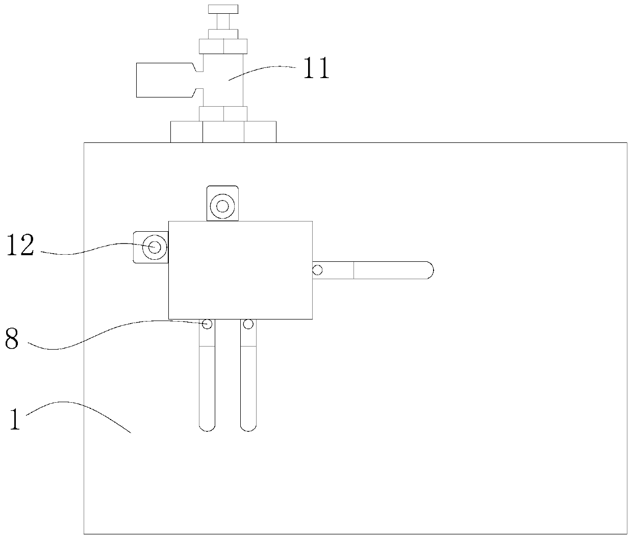
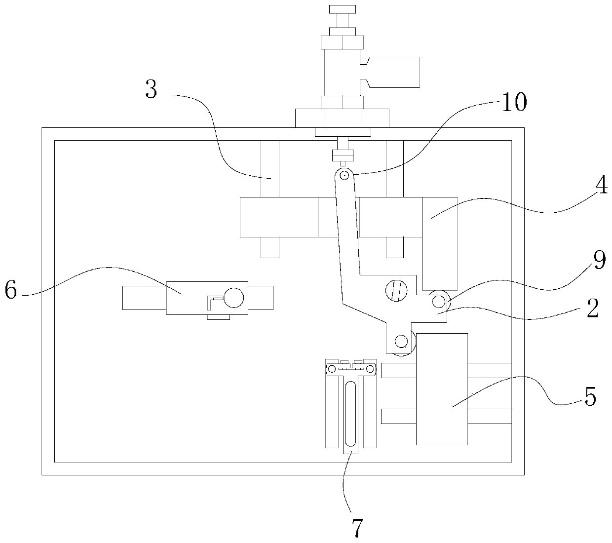
[0018] see Figure 1-2 , a self-positioning resistance repair fixture,.

[0019] When in use, place the chip that needs to be retrogradely repaired in the area surrounded by the limiting column and the second rotating shaft. After the chip is placed, after the first correction, when the chip is repositioned, slide the second After a fixed block 6 or the second fixed block 7 supports the chip, at this time, as the first fixed block 6 or the second fixed block 7 transmits the force to the second rotating shaft 12 through the chip when the chip is pushed, the second rotating shaft 12 moves under the condition of force, and drives the first moving block 4 or the second moving block 5 to move on the slide bar 3 through the second rotating shaft 12. As the first moving block 4 move...


PUM


Abstract

The invention relates to the technical field of laser resistance repair, and discloses a self-positioning resistance repairing fixture. The self-positioning resistance repairing fixture comprises a main board, wherein a limiting block is movably mounted inside the main board through a rotating shaft, and sliding rods are fixedly mounted on both sides of the limiting block. According to the self-positioning resistance repairing fixture, a rectangular groove inside a first moving block is in contact with the limiting block, so that the limiting block can be rotated, and the first moving block and a second moving block can be simultaneously limited and fixed through the right angle groove. Similarly, as the movement of the second moving block, the right-angled edge of the limiting block is enabled to be gradually aligned with the second moving block, the other end of the limiting block is aligned with the first moving block, a chip is clamped, and the automatic positioning is realized byadjusting the position of a second rotating shaft on either side, and automatically adjusting the position of the other moving block by rotation of the limiting block, so that the problem of too highproduct scrap rate caused by that the path deviation occurs when the laser resistance is repaired due to excessive positioning error of a product during re-positioning is avoided.

Description

technical field [0001] The invention relates to the technical field of laser resistance repairing, in particular to a self-positioning resistance repairing jig. Background technique [0002] Laser resistance repair is to position a beam of focused coherent light on the workpiece under the control of a microcomputer, so that the film layer of the workpiece to be adjusted is gasified and removed to achieve the specified parameters or resistance value. When the resistance is adjusted, the local temperature rise makes the glass melt, and the edge of the gasification part of the resistance value groove is covered by glass, which can fill up the cut medium on the surface of the substrate. [0003] When repairing the ceramic chip of the oil level sensor, since the maximum width of the ceramic chip of the oil level sensor is only 0.16m in width, and the minimum spot diameter of the current laser resistance repairing machine is only 0.08mm in diameter, the relative gap margin after r...

Claims


Application Information

Patent Timeline
Patent Type & Authority Applications(China)
IPC IPC(8): G01F23/00H01C17/242
Inventor 杨然非
Owner 广德方晟科技有限公司
Why Eureka
Try Eureka