Unmanned vehicle, and unmanned vehicle positioning method, device and system
An unmanned vehicle and positioning technology, applied in the field of unmanned vehicles and vehicle engineering, can solve the problems of inability to provide high-precision and high-stability positioning results, large positioning errors, etc., and achieve the effect of avoiding large positioning errors and accurate positioning.
- Summary
- Abstract
- Description
- Claims
- Application Information
AI Technical Summary
Problems solved by technology
Method used
Image


Examples
Embodiment Construction
[0021] The application will be further described in detail below in conjunction with the accompanying drawings and embodiments. It should be understood that the specific embodiments described here are only used to explain related inventions, rather than to limit the invention. It should also be noted that, for the convenience of description, only the parts related to the related invention are shown in the drawings.
[0022] It should be noted that, in the case of no conflict, the embodiments in the present application and the features in the embodiments can be combined with each other. The present application will be described in detail below with reference to the accompanying drawings and embodiments.
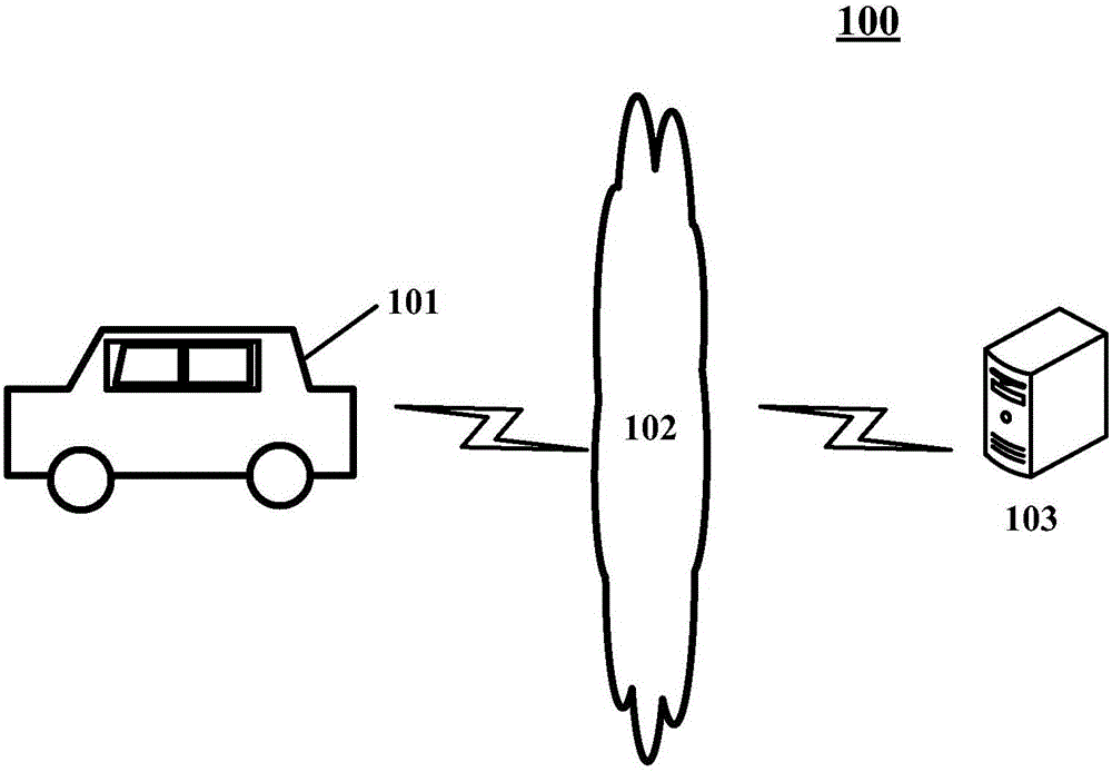
[0023] figure 1 An exemplary system architecture 100 of an embodiment of the unmanned vehicle positioning method based on laser point cloud reflection value matching or the unmanned vehicle positioning device based on laser point cloud reflection value matching of the presen...
PUM
 Abstract
Description
Claims
Application Information