Method for combining resource allocation and content caching in F-RAN architecture

A technology for content caching and resource allocation, which is applied in the field of joint resource allocation and content caching, can solve problems such as waste of cache resources, inability to guarantee service delay, waste of spectrum resources, etc., and achieve the goal of reducing the pressure on fronthaul links and improving resource utilization Effect

Active Publication Date: 2019-06-28
CHONGQING UNIV OF POSTS & TELECOMM
11 Cites 12 Cited by

AI-Extracted Technical Summary

Problems solved by technology

[0004] Most of the existing research literature on resource allocation and content caching of network slicing has no Considering the impact of their dynamic and randomness on resource allocation and caching; without considering the impact of the current time slot decision on future resource allocation and content caching strategies, if the frequently requested content of the network slice is cached, spectrum resources will be saved , if you cache content...

Abstract

The present invention relates to a method for combining resource allocation and content caching in an F-RAN architecture, and belongs to the field of mobile communication. The method comprises the following steps of: in an F-RAN scene, while content service delay and network slice SLA constraint are ensured, carrying out network slice wireless resource allocation and content caching decision by taking maximization of long-term average effectiveness of the system as a target; in each discrete time slot, according to length state of a content request virtual queue of an edge fog node of a current time slot and state information of network slice content transmission capability of a forward link and a wireless access link, allocating proper wireless resources for each network slice dynamicallywithin limitation of wireless resource capacity and cache capacity, and caching the content requested by the network slices at the edge fog node. According to the method and the device, the content service delay and the network slice SLA can be ensured, meanwhile, the forward link pressure is reduced, and the resource utilization rate is increased.

Application Domain

Technology Topic

Current timeWireless resource allocation +9

Image

  • Method for combining resource allocation and content caching in F-RAN architecture
  • Method for combining resource allocation and content caching in F-RAN architecture
  • Method for combining resource allocation and content caching in F-RAN architecture

Examples

  • Experimental program(1)

Example Embodiment

[0039] The preferred embodiments of the present invention will be described in detail below with reference to the accompanying drawings.
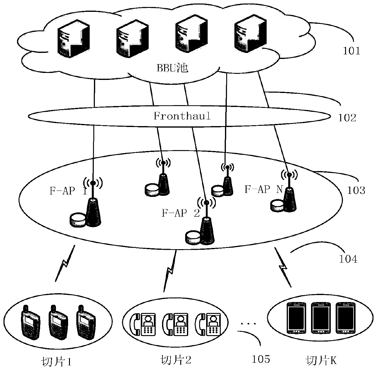
[0040] see figure 1 shown, figure 1It is an F-RAN scene diagram, including five parts: BBU pool 101, used for processing baseband signals; fronthaul fronthaul link 102, which is a wired transmission link, connecting BBU and edge fog node 103; edge fog node 103 has computing, Edge network equipment with caching and communication capabilities; wireless access link 104 is a communication link that wirelessly connects users in network slices to edge fog nodes 103 ; content requests dynamically arriving in network slices 105 are queued at edge fog nodes 103 . The edge fog node 103 determines resource allocation and content based on information such as the length of the virtual queue established for the content and the data rate of the content transmitted by the fronthaul link and the wireless access link, and comprehensively considers the possible impact of the current decision on future rewards. Caching strategies to maximize the long-term average total utility of the system. If the edge fog node 103 caches a certain content, when the network slice 105 requests the content, it will directly send it to the network slice; if the edge fog node 103 does not cache a certain content, when the network slice 105 requests the content, it needs to The baseband signal is processed by the BBU pool 101 , and then the content is transmitted to the edge fog node 103 connected to the network slice 105 through the fronthaul link 102 , and finally sent to the network slice 105 through the wireless access link 104 . Since the decision of the current time slot will affect the future resource allocation and content caching strategy, if the edge fog node 103 caches the content frequently requested by the network slice 105, it will save wireless resources. , it will cause a waste of cache resources, resulting in no space to cache the content that should be cached, thus wasting wireless resources.
[0041] see figure 2 shown, figure 2 It is the virtual queue diagram of the network slice content request at the edge fog node. The arrival process of the network slice content request 201 obeys the Poisson distribution, and then each content request enters the corresponding content request virtual queue according to the edge fog node connected to the network slice. 203 , the arrival rate of each content request virtual queue 203 is 202 , and the number of content requests leaving the content request virtual queue 203 is related to the resource allocation of the current time slot and the content caching strategy 204 . If the current time slot edge fog node caches the content, that is α nf (t)=1, then the content request leaves the number D nf (t) The number of radio resources currently allocated for all network slices β knf (t) The content data rate r sent to the network slice by the edge fog node through the wireless link knf The sum of the products of (t), i.e. If the current time slot edge fog node does not cache the content, that is α nf (t)=0, then the content request leaves the number D nf (t) The number of radio resources currently allocated for all network slices β knf (t) The content data rate transmitted to the edge fog node through the fronthaul link with the BBU pool and then sent to the network slice through the wireless link The sum of the products of , that is Ensuring the service delay of the content request means ensuring that the content request of the network slice is not discarded. According to the little theorem, it can be described as ensuring that the long-term average length of the virtual queue 203 for content requests is not greater than a certain value.
[0042] see image 3 shown, image 3 Defining graphs for the pre-decision state and post-decision state also reflects the relationship between the two. The pre-decision state 301 of the current time slot is the content request virtual queue length state at the edge fog node and the data rate state of the content transmitted by the fronthaul link and the wireless access link in the current time slot; the post-decision state 302 in the current time slot, It is a tentative virtual state, which is the state of the system after the resource allocation and cache configuration behaviors are implemented 304 and before the network slice content request reaches 305, where the content request virtual queue length state at the edge fog node is content request at this time. In the queue length state that leaves and a new content request has not arrived, the data rate of the content transmitted by the fronthaul link and the wireless access link remains unchanged in the current time slot. The post-decision state 302 describes how many wireless resources need to be allocated to each network slice and whether the edge fog node caches the content required by the network slice; the pre-decision state 303 at the beginning of the next time slot is a virtual queue for content request at the edge fog node The status after the length update and the data rate status of the content transmitted by the new fronthaul link and radio access link reflect the impact of the arrival of network slice content requests on the network. The relationship between the post-decision state and the pre-decision state is that the post-decision state 302 value function of the current time slot is equal to the pre-decision state 303 value function at the beginning of the transfer to the next time slot, and the mathematical average is obtained; the introduction of the post-decision state 302 avoids the problem of solving The dependence of the Bellman equation in MDP on the state transition probability reflects the statistical characteristics of random variables in the external environment; the resource allocation and content caching strategy can be obtained by updating the state 302 value function online after the decision is made through the stochastic gradient method.
[0043] Figure 4 To update the flow chart online for the post-decision state value function, the steps are as follows:
[0044] Step 401: Initialize the value function of all possible post-decision states;
[0045] Step 402: Initialize Lagrange multipliers and learning factors;
[0046] Step 403: Initialize time slot t;
[0047] Step 404: Initialize the content request virtual queue length of all edge fog nodes;
[0048] Step 405: set the reference state;
[0049] Step 406: Observe status information such as the number of content requests for each network slice in the current time slot and the data rate of the content transmitted by the fronthaul link and the wireless access link;
[0050] Step 407: Comprehensively consider the current network state information and the possible impact of the decisions made on future rewards, randomly select a strategy for resource allocation and content caching with probability ∈, and find the state value function that maximizes the state value function after the decision with a probability of 1-∈. Approach the real pre-decision state value function of resource allocation and content caching decisions, and determine the optimal resource allocation and content caching strategy to maximize the long-term average total utility of the system;
[0051] Step 408: Calculate and record the maximum system utility obtained by adopting the optimal resource allocation and content caching strategy in the current time slot;
[0052] Step 409: Update the value function of the post-decision state of the current time slot;
[0053] Step 410: According to the current iteration, judge whether the convergence condition is met. If the obtained decision, that is, the resource allocation and content caching strategy, can maximize the long-term average utility of the system and satisfy the convergence condition, skip to step 412; if the obtained decision does not If the convergence condition is satisfied, then jump to step 411;
[0054] Step 411: Update variables such as Lagrangian multiplier, learning factor, time slot, virtual queue length, etc. for the next iteration;
[0055] Step 412: Output the optimal resource allocation and content caching decision and the maximum post-decision state value function.
[0056] Finally, it should be noted that the above preferred embodiments are only used to illustrate the technical solutions of the present invention and not to limit them. Although the present invention has been described in detail through the above preferred embodiments, those skilled in the art should Various changes may be made in details without departing from the scope of the invention as defined by the claims.

PUM

no PUM

Description & Claims & Application Information

We can also present the details of the Description, Claims and Application information to help users get a comprehensive understanding of the technical details of the patent, such as background art, summary of invention, brief description of drawings, description of embodiments, and other original content. On the other hand, users can also determine the specific scope of protection of the technology through the list of claims; as well as understand the changes in the life cycle of the technology with the presentation of the patent timeline. Login to view more.

Similar technology patents

Method for recovery of rare earth by low concentration rare earth solution extraction

ActiveCN104294063AEfficient Clean ExtractionImprove resource utilizationProcess efficiency improvementHigh concentrationRaffinate
Owner:GENERAL RESEARCH INSTITUTE FOR NONFERROUS METALS BEIJNG +1

Classification and recommendation of technical efficacy words

Why Eureka
Try Eureka