Ring welding equipment

A kind of equipment, the technology of girth welding, applied in welding equipment, auxiliary welding equipment, welding/cutting auxiliary equipment, etc., can solve the problems of scalding, human body easy to cause injury, low welding efficiency and so on

Pending Publication Date: 2019-07-02
佛山市欧朗智能装备有限公司
View PDF0 Cites 2 Cited by
  • Summary
  • Abstract
  • Description
  • Claims
  • Application Information

AI Technical Summary

Problems solved by technology

[0004] At present, more and more stainless steel products are used to replace iron products, especially with the characteristics of corrosion resistance. Some pipe fittings and pipe fittings are made of stainless steel. When welding pipe fittings, the traditional method is to manually install the fittings on the machine. Then the welding is performed on the manual control machine, the welding...

Method used


Image

  • Ring welding equipment
  • Ring welding equipment
  • Ring welding equipment

Examples


Embodiment 1

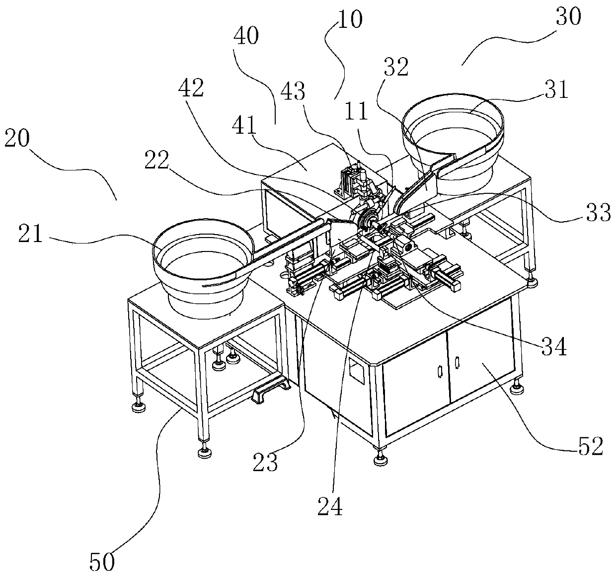
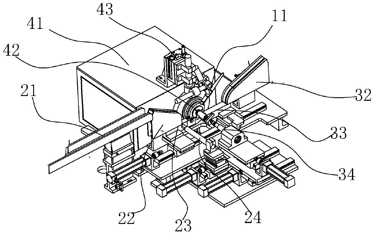
[0022] Such as Figure 1-3 As shown, a girth welding equipment of this embodiment includes a welding gun 10, a first workpiece feeding device 20, a second workpiece feeding device 30, and a pneumatic chuck 40. The first workpiece feeding device includes a first vibration feeding device. The disc 21, the first feeding trough 22, the first feeding rod 23 and the first pushing mechanism 24. The first feeding rod 23 is provided with a first clamping port. One end of the first feeding trough 22 is connected to the first feeding rod 23. The vibrating feeding tray 21 is connected, and the other end is set directly above the first feeding rod 23, and the first feeding rod 23 can move relative to the first unloading trough 22, and the first workpiece is dropped from the first unloading trough 22 in an orderly manner And it just falls to the first clamping port, and each time there is one and only one falling on the first clamping port, the first feeding rod 23 pushes the first workpiece...

Embodiment 2

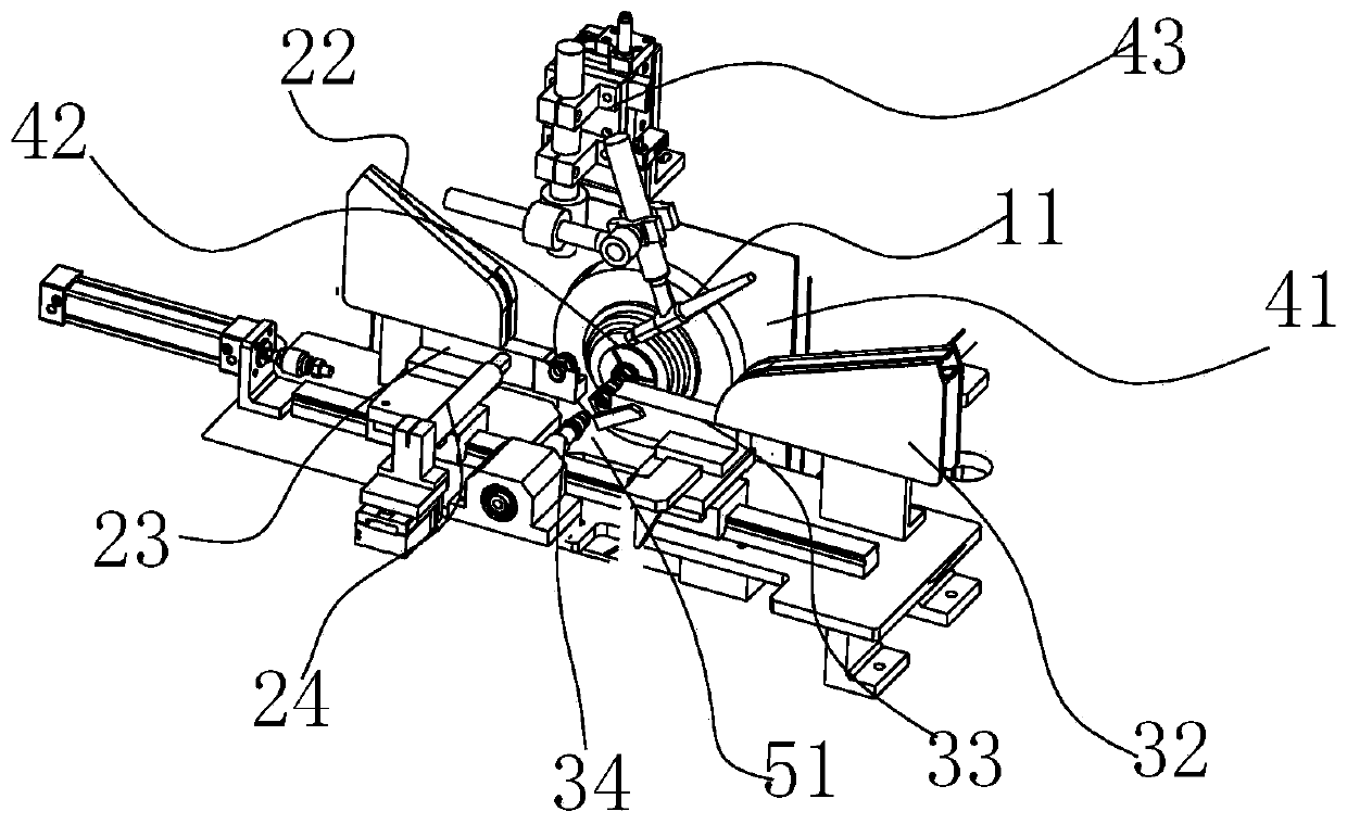
[0028] Such as Figure 1-3 As shown in the circular welding equipment of this embodiment, the welding gun 10 includes a gun head 11, the gun head 11 is installed on the work box 41 by a lift 43, and the gun head 11 can move up and down relative to the locking mechanism 42. The main purpose of the design of this structure is to facilitate the movement of the first feeding rod 33 and the second pushing mechanism 34. After the welding is completed, the gun head 11 of the welding gun 10 moves upward through the elevator 43 to wait for welding. When the feeding is completed, the gun head 11 Lowering for welding, so that each component will not hinder each other.

Embodiment 3

[0030] Such as image 3 As shown, the girth welding equipment of this embodiment further includes a workbench 50. The first workpiece feeding device 20, the second workpiece feeding device 30, and the pneumatic chuck 40 are all installed on the workbench 50. The table 50 is located directly below the locking mechanism 43 and is provided with a discharge port 51. The welded workpiece is automatically discharged from the discharge port 51. The main purpose of this structural design is to allow the workpiece to fall freely after the welding is completed. Object space is convenient for the collection of workpieces.


PUM


Abstract

The invention mainly relates to pipe fitting welding equipment, in particular to ring welding equipment. The ring welding equipment comprises a welding gun, a first workpiece feeding device, a secondworkpiece feeding device and a pneumatic chuck. According to the ring welding equipment, through the first workpiece feeding device and the second workpiece feeding device, a first workpiece is fed toa locking mechanism through the joint cooperation of a first feeding rod and a first pushing mechanism, a second workpiece is moved to be aligned and spliced with the first workpiece through a secondfeeding rod and a second pushing structure, a welding gun welds a gap between the first workpiece and the second workpiece, and a second pushing mechanism and the pneumatic chuck simultaneously drivethe first workpiece and the second workpiece to rotate, so that the welding is completed. Compared with traditional manual feeding and discharging welding equipment, automatic feeding and dischargingfunctions are realized, and the automatic welding can be realized after the feeding and discharging are completed, so that the production efficiency is greatly improved, the labor cost is reduced, the harm to a human body facing the welding equipment for a long time is reduced, and the automatic welding of pipe fittings is realized.

Description

[0001] 【Technical Field】 [0002] The present invention mainly relates to pipe welding equipment, in particular to a girth welding equipment. [0003] 【Background technique】 [0004] At present, more and more stainless steel products are replacing iron products, especially with the characteristics of corrosion resistance. Stainless steel is used to make some pipe fittings and pipe fittings. When pipe fittings are welded, the traditional method is to manually install the fittings on the machine. Then the welding is performed by manually controlling the machine. The efficiency of welding is low, and long-term operation of the welding machine is easy to cause harm to the human body. After the welding is completed, the pipe must be manually removed from the machine, and it may be burned, which not only increases labor costs, but also It will bring certain dangers to workers, and there is an urgent need for a welding equipment capable of automatic loading and unloading and automatic weldi...

Claims


Application Information

Patent Timeline
IPC IPC(8): B23K37/00B23K37/053B23K37/02B23K103/04B23K101/06
CPCB23K37/00B23K37/02B23K37/0538
Inventor 蓝信锦温利明钟方庆
Owner 佛山市欧朗智能装备有限公司
Why Eureka
Try Eureka