A fully automatic assembly conveyor line for power distribution cabinets

A fully automatic, conveying line technology, applied in metal processing equipment, metal processing, manufacturing tools, etc., can solve problems such as inability to perform fully automatic assembly work, and achieve the effects of stable work, reduced production costs, and easy control.

Active Publication Date: 2020-05-26
国网甘肃省电力公司甘南供电公司
View PDF5 Cites 0 Cited by
  • Summary
  • Abstract
  • Description
  • Claims
  • Application Information

AI Technical Summary

Problems solved by technology

[0005] The purpose of the present invention is to address the deficiencies of the prior art. By setting an automatic assembly mechanism, the zero wire is bent and formed and then automatically installed on the wiring board and switch. The locking work of the line solves the technical problem that the automatic assembly work cannot be carried out when the zero line is assembled with the switch and the wiring board respectively

Method used


Image

  • A fully automatic assembly conveyor line for power distribution cabinets
  • A fully automatic assembly conveyor line for power distribution cabinets
  • A fully automatic assembly conveyor line for power distribution cabinets

Examples


Embodiment 1

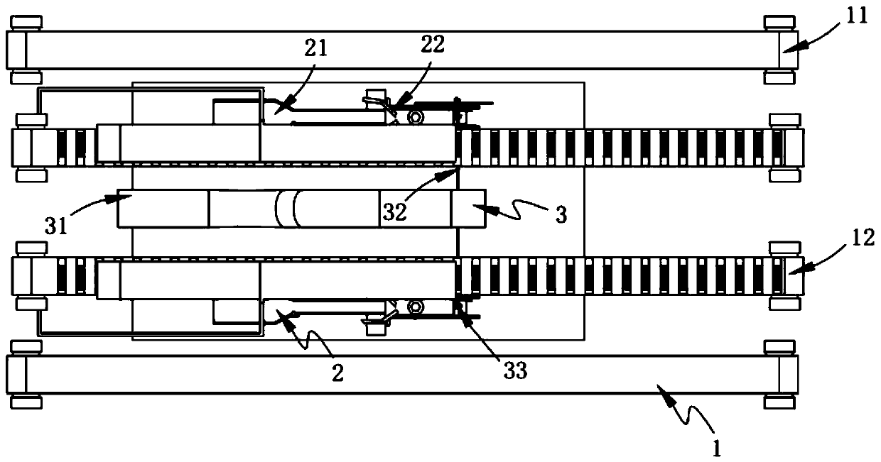
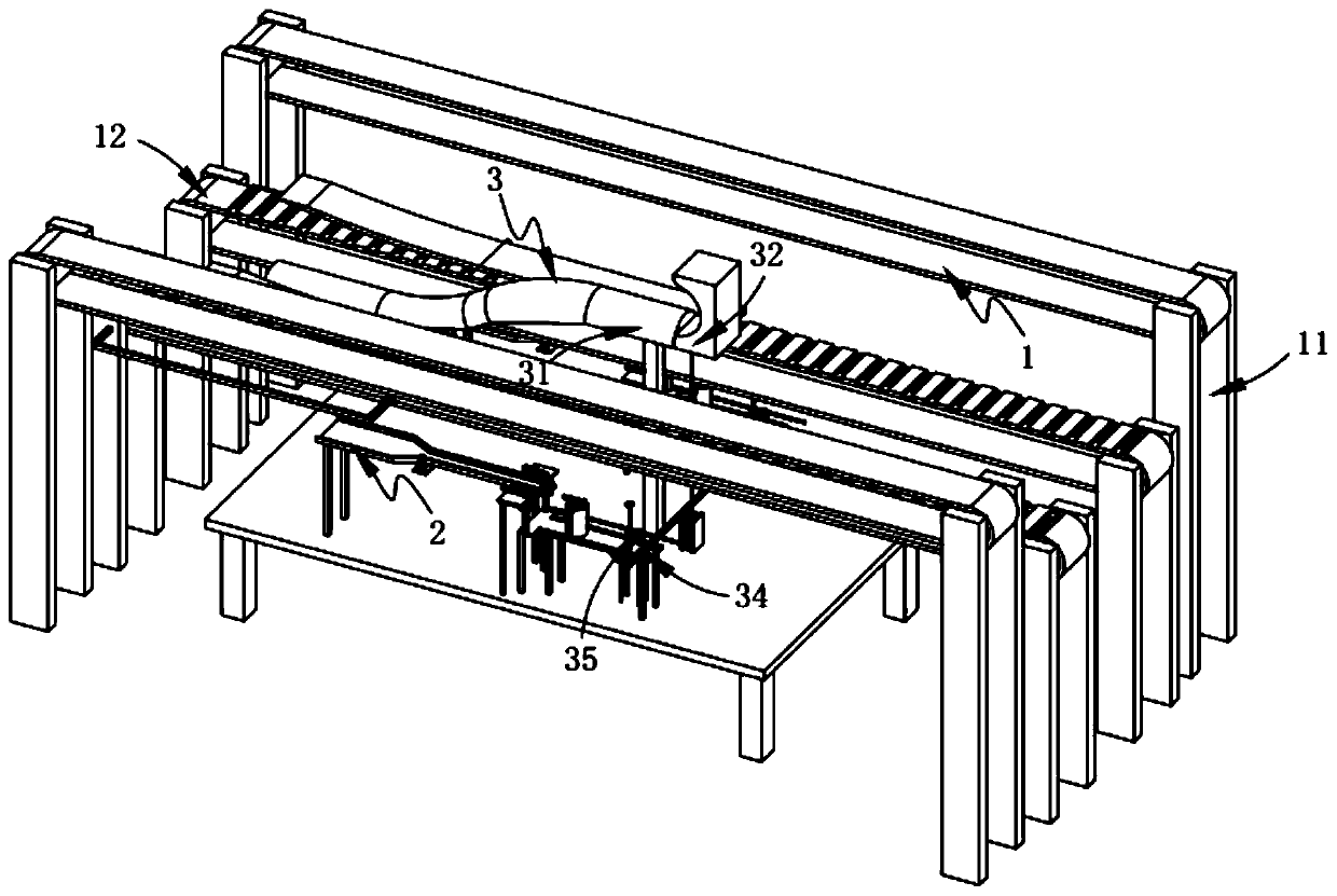
[0064] Such as figure 1 , figure 2 As shown, a fully automatic assembly conveyor line for power distribution cabinets includes:

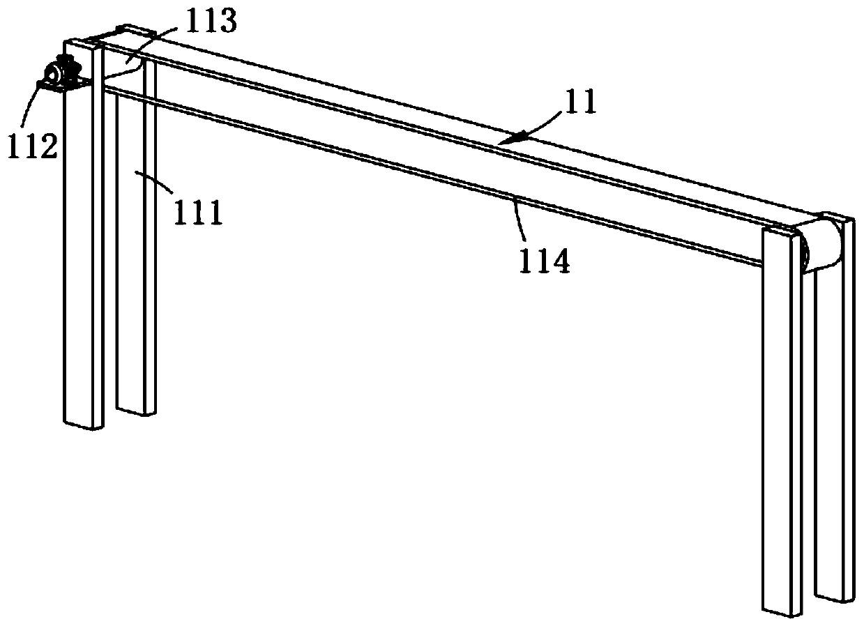
[0065] A raw material transfer mechanism 1, the raw material transfer mechanism 1 includes a workpiece feeding assembly 11 arranged symmetrically and a zero-line feeding assembly 12 arranged along the width direction of the workpiece feeding assembly 11 and symmetrically arranged on both sides of the workpiece feeding assembly 11 ;

[0066] Nut transmission mechanism 2, said nut transmission mechanism 2 includes arrangement components 21 symmetrically arranged on both sides of said raw material transmission mechanism 1 and arranged in the same direction as said raw material transmission mechanism 1, and arranged at the output end of said arrangement assembly 21 Intermittent component 22; and

[0067] An automatic assembly mechanism 3, the automatic assembly mechanism 3 includes a forming assembly 31 arranged between the workpiece feeding assemblies 11, a...

Embodiment 2

[0110] Such as Figure 16 , Figure 15 As shown, the components that are the same as or corresponding to those in the first embodiment use the reference numerals corresponding to those in the first embodiment. For the sake of simplicity, only the differences from the first embodiment are described below. The difference between the second embodiment and the first embodiment is:

[0111] Further, such as Figure 16 , Figure 15 As shown, the first transmission assembly 34 includes:

[0112] The linkage a341 is symmetrically arranged on both sides of the pusher assembly 32 and is mounted on the mounting seat 311, and includes a leg a3411, a rotating shaft d3412 that is rotatably arranged on the leg a3411 A gear b3413 coaxially and fixedly arranged with the rotating shaft d3412, a gear c3414 coaxially and fixedly arranged with the gear b3413, and a rack b whose one end is fixedly connected to the intermittent component 22 and meshes with the gear b3413 to rotate; as well as

[0113] ...


PUM


Abstract

The invention relates to a full-automatic assembly transmission line for a power distribution cabinet. The full-automatic assembly transmission line comprises a raw material transmission mechanism, ascrew cap transmission mechanism and an automatic assembling mechanism, wherein the raw material transmission mechanism comprises workpiece feeding assemblies which are symmetrically arranged on the left side and the right side and null line feeding assemblies which are arranged in the width directions of the workpiece feeding assemblies and are symmetrically arranged on the two sides of the workpiece feeding assemblies; the screw cap transmission mechanism comprises arrangement assemblies which are symmetrically arranged on the two sides of the raw material transmission mechanism and are arranged in the same direction as the direction of the raw material transmission mechanism and intermittent assemblies which are arranged at the output ends of the arrangement assemblies; the automatic assembling mechanism comprises a formation assembly which is arranged between the workpiece feeding assemblies, a top-feeding assembly which is mounted on the formation assembly, a fastening assembly which is fixedly connected with the top-feeding assembly, a first transmission assembly which is linked with the top-feeding assembly and a second transmission assembly which is linked with the first transmission assembly. By adopting the full-automatic assembly transmission line disclosed by the invention, the technical problem is solved.

Description

Technical field [0001] The invention relates to the technical field of power distribution cabinets, in particular to a fully automatic assembly transmission line for power distribution cabinets. Background technique [0002] The power distribution cabinet is the general name of the motor control center. The power distribution cabinet is used in the occasions where the load is relatively dispersed and the circuit is less; the motor control center is used in the occasions where the load is concentrated and the circuit is more. The electric energy is distributed to the nearby load. This level of equipment should provide protection, monitoring and control of the load. [0003] The patent document with the patent number CN8616050A discloses a multifunctional intelligent power distribution cabinet, including a cabinet body, a base, a rain shield and a cabinet door. The four corners of the cabinet body are equipped with vertical adjustable legs; A number of compressed shock-absorbing spr...

Claims


Application Information

Patent Timeline
Patent Type & Authority Patents(China)
IPC IPC(8): B23P19/00
CPCB23P19/001
Inventor 王子轩成金雷尹尚陈建清
Owner 国网甘肃省电力公司甘南供电公司
Why Eureka
Try Eureka