Transmission shaft of sewing machine

A transmission shaft and sewing machine technology, which is applied to sewing machine components, sewing machine control devices, sewing equipment, etc., can solve the problems of large size of moving shaft seat, large space occupied, and increased cost, so as to achieve flexible use, save input cost, The effect of saving material usage

Inactive Publication Date: 2019-07-02
王芳
View PDF0 Cites 0 Cited by
  • Summary
  • Abstract
  • Description
  • Claims
  • Application Information

AI Technical Summary

Problems solved by technology

[0004] A shuttle shaft (i.e. a transmission shaft) cooperating with the machine needle is installed inside the table, and the shuttle shaft moves axially inside the table to achieve the purpose of thread feeding. One end rotates, therefore, the two ends of the shuttle shaft are respectively provided with a moving shaft seat, and a shaft hole is provided on the moving shaft seat. At the same time, the strength of the shaft seat separates the hook shaft from other parts when it rotates. However, because the moving shaft seat is far away from the body of the hook shaft, the size of the moving shaft seat is relatively large, and the space it occupies is also large. When the shuttle shaft rotates, it collides with other parts. During production and processing, the material used in this part is also more, resulting in an increase in investment costs.

Method used


Image

  • Transmission shaft of sewing machine
  • Transmission shaft of sewing machine
  • Transmission shaft of sewing machine

Examples


Embodiment Construction

[0014] The following are specific embodiments of the present invention and in conjunction with the accompanying drawings, the technical solutions of the present invention are further described, but the present invention is not limited to these embodiments.

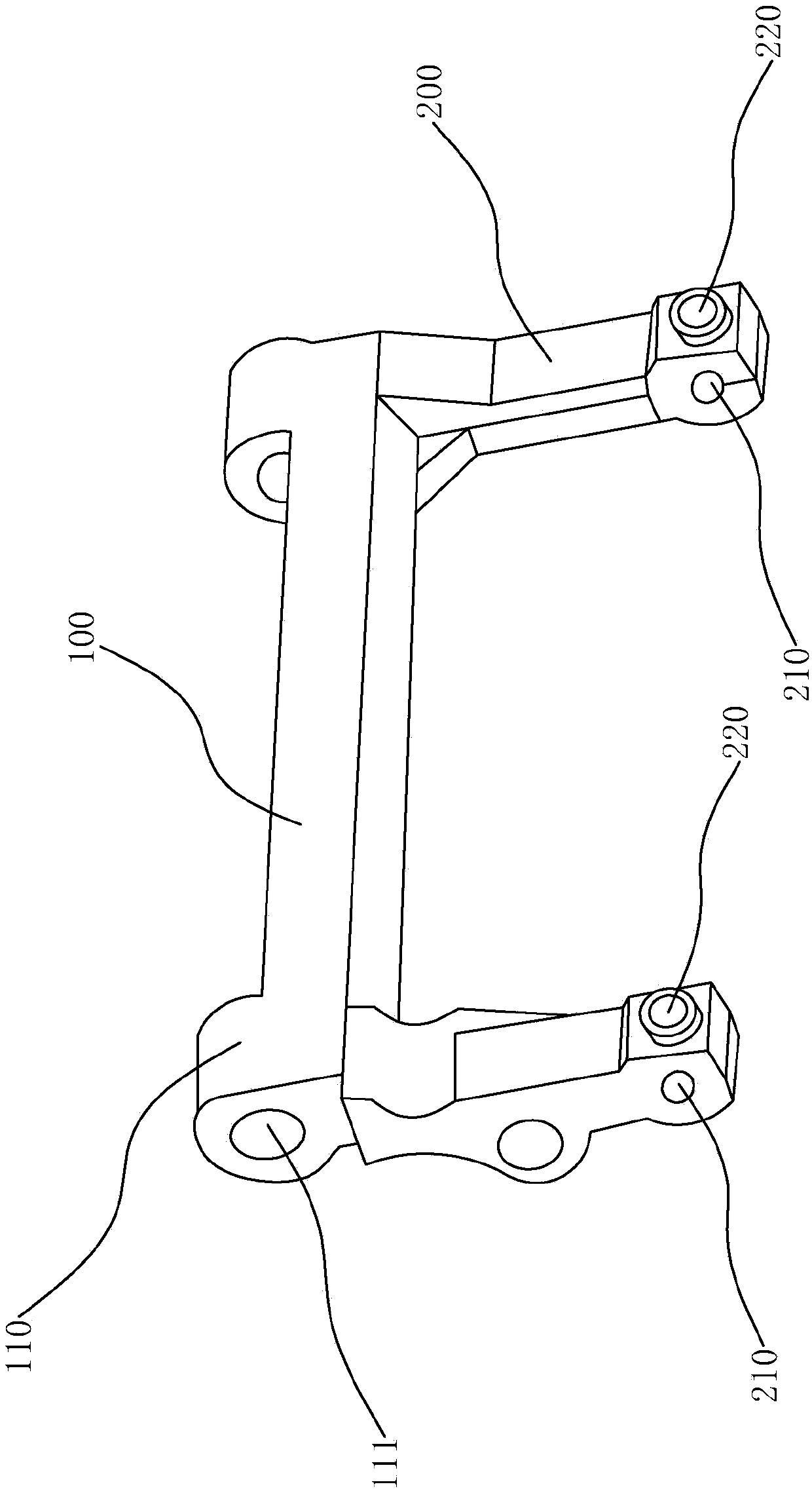
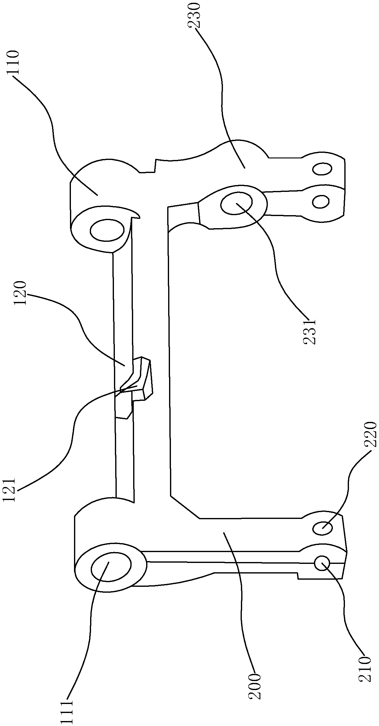
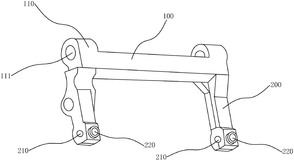
[0015] Such as figure 1 , figure 2 As shown, a sewing machine transmission shaft includes a main shaft 100 and connecting arms 200 respectively arranged at two ends of the main shaft 100 and parallel to each other. A coaxial shaft hole 111 is opened axially on the moving shaft seat 110, and a connecting hole 210 is opened axially at one end of the two connecting arms 200, and the two connecting holes 210 are coaxial. arc-shaped groove 120, the arc-shaped groove 120 is arranged along the axial direction and the two ends are respectively connected with the connecting arm 200, the inwardly recessed groove 121 is arranged on the arc-shaped groove 120, and the connecting arm 200 is provided with The threaded hole 220 and the...


PUM


Abstract

The invention provides a transmission shaft of a sewing machine, belonging to the technical field of sewing machines. The invention aims at solving the technical problems that in the existing horizontal transmission shaft, a movable shaft seat is larger in volume and higher in overall production cost. The transmission shaft of the sewing machine is characterized in that the transmission shaft of the sewing machine comprises a main shaft and connecting arms which are respectively arranged at the two ends of the main shaft and are parallel to each other; the two ends of the main shaft separatelyextend to the same side so as to form movable shaft seats; the two movable shaft seats are provided with coaxial axle holes along the axial direction; one ends of the two connecting arms are respectively and coaxially provided with connecting holes, and the two connecting holes are coaxial; the main shaft is provided with an arc-shaped groove along the transverse direction, and the arc-shaped groove is coaxial with the axle holes; the arc-shaped groove is formed along the axial direction, and the two ends of the arc-shaped groove are respectively connected with the connecting arms; the arc-shaped groove is provided with a groove sinking inwards; each connecting arm is provided with a threaded hole, and the threaded holes are communicated with the connecting holes. The transmission shaft of the sewing machine has the beneficial effects that the sizes and space volumes of the movable shaft seats are effectively reduced, the material input is reduced, and certain cost is lowered.

Description

technical field [0001] The invention belongs to the technical field of sewing machines, and relates to a sewing machine transmission shaft. Background technique [0002] A sewing machine is a machine that uses one or more sewing threads to form one or more stitches on the sewing material to interweave or sew one or more layers of sewing material. The sewing machine can sew fabrics such as cotton, fiber crops, silk, wool, and artificial fibers, and products such as leather, plastics, and paper. [0003] The transmission part of the existing sewing machine is composed of components such as a frame, a hand crank or a motor. The frame is the pillar of the machine, supporting the platen and the pedals. During use, the operator steps on the pedals to drive the pulley through the crank The rotation of the chicken is driven by the belt to rotate the chicken head, and most of the hand crank or motor are directly installed on the head. [0004] A shuttle shaft (i.e. a transmission s...

Claims


Application Information

Patent Timeline
Patent Type & Authority Applications(China)
IPC IPC(8): D05B69/02D05B69/30
CPCD05B69/02D05B69/30
Inventor 王芳
Owner 王芳
Why Eureka
Try Eureka