
Angular travel adjusting valve

A technology for regulating valves and angular strokes, which is applied in the direction of lift valves, valve devices, engine components, etc. It can solve the problems of large valve stem partial load, angular stroke regulating valve switch take-off, etc., and achieve the effect of avoiding the decline of sealing performance

Inactive Publication Date: 2019-07-02
重庆昂宇自控仪表有限公司
View PDF7 Cites 1 Cited by
  • Summary
  • Abstract
  • Description
  • Claims
  • Application Information

AI Technical Summary

Problems solved by technology

[0003] In view of the above-mentioned shortcomings of the prior art, the purpose of the present invention is to provide a quarter-stroke regulating valve, which is used to solve the problem of large unbalanced load on the valve stem of the straight-stroke regulating valve and the switch-off of the quarter-stroke regulating valve in the prior art. question

Method used


Image

  • Angular travel adjusting valve
  • Angular travel adjusting valve
  • Angular travel adjusting valve

Examples


Embodiment Construction

[0043] Embodiments of the present invention are described below through specific examples, and those skilled in the art can easily understand other advantages and effects of the present invention from the content disclosed in this specification. The present invention can also be implemented or applied through other different specific implementation modes, and various modifications or changes can be made to the details in this specification based on different viewpoints and applications without departing from the spirit of the present invention.

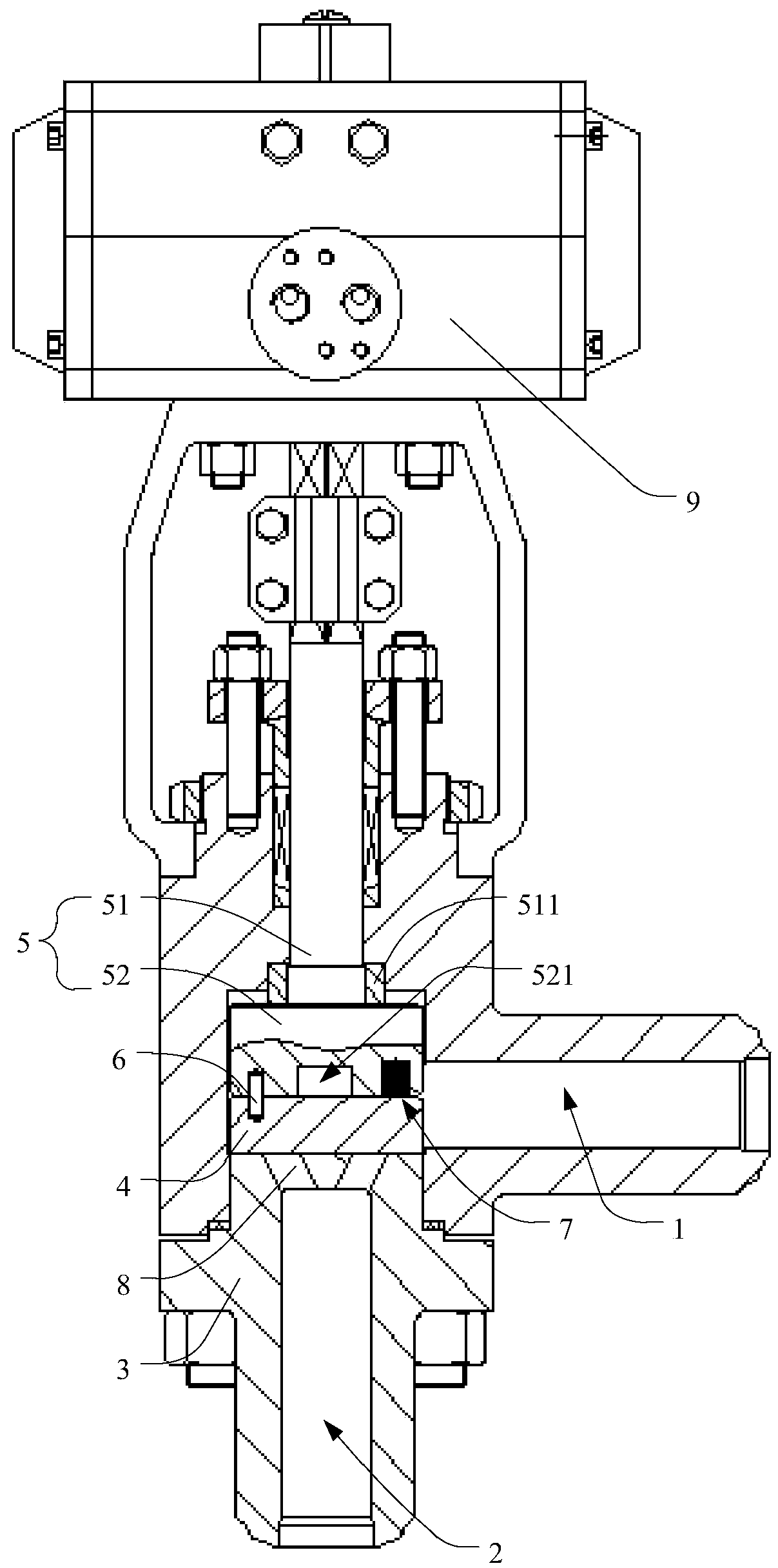
[0044] see Figure 1 to Figure 4 . It should be noted that the diagrams provided in this embodiment are only schematically illustrating the basic idea of ​​the present invention, and only the components related to the present invention are shown in the diagrams rather than the number, shape and shape of the components in actual implementation. Dimensional drawing, the type, quantity and proportion of each component can be changed arb...


PUM


Abstract

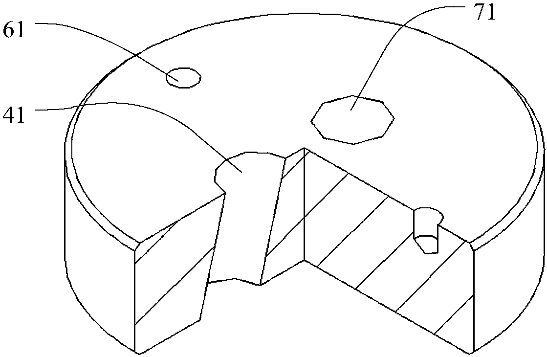
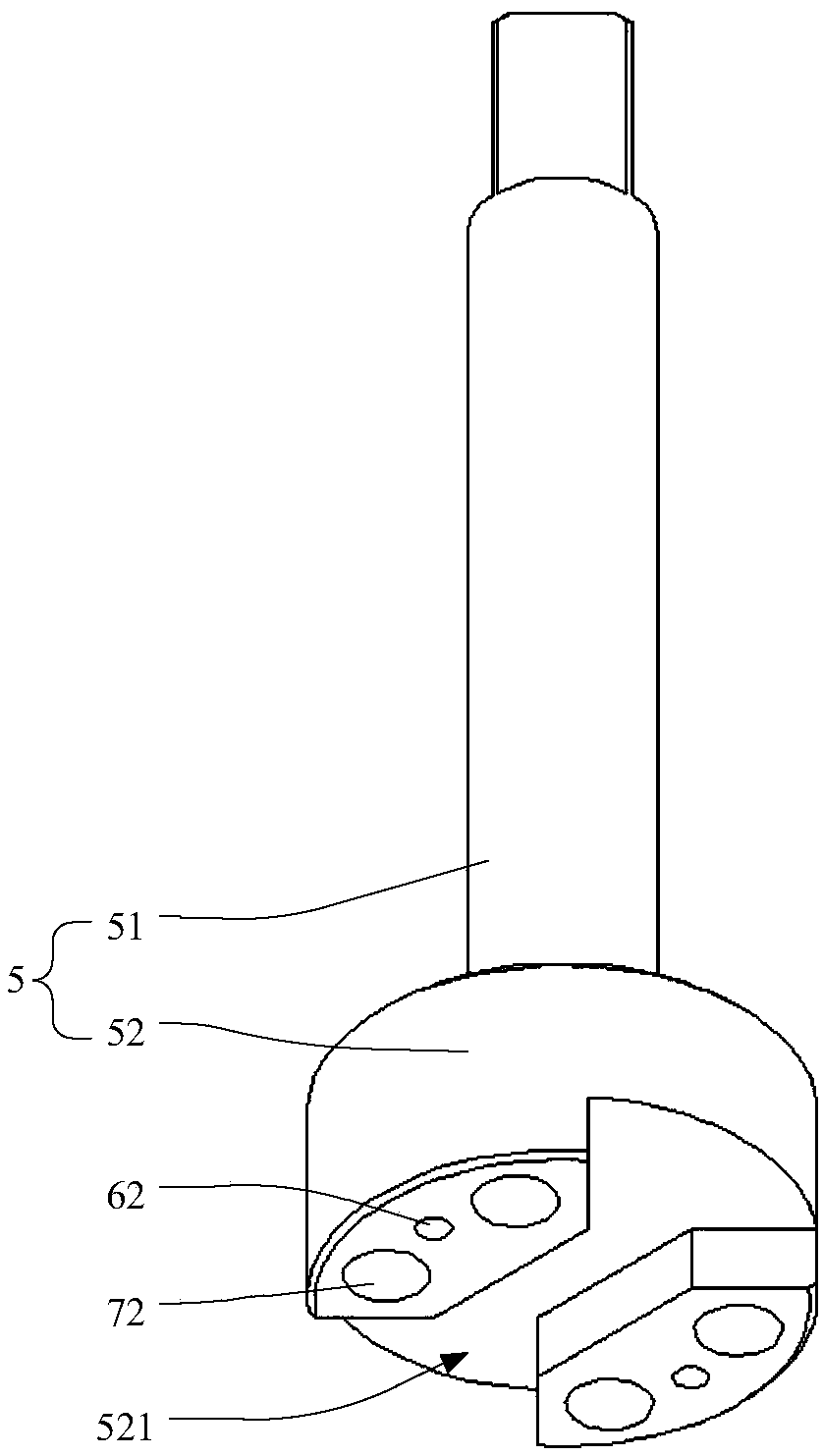
The invention provides an angular travel adjusting valve, which comprises a first valve channel, a second valve channel, a valve rod, a valve element and a valve seat. The valve rod and the valve element are arranged in the valve seat, by rotating the valve rod, the valve element can be driven to rotate, the first valve channel communicates with a flow-guiding groove in the valve rod, the flow-guiding groove communicates with the second valve channel through a flow channel hole in the valve element, thus the angular travel adjusting valve is opened, by revolving the valve rod, the angular travel adjusting valve can be closed, the plane, close to the second valve channel, of the valve element serves as a sealing face to plug the second valve channel or communicate with the second valve channel, the phenomenon of unbalance loading of the valve rod or switch tripping is avoided, the applicability and compatibility of the travel adjusting valve are improved, and manufacturing, using and popularizing are convenient.

Description

technical field [0001] The invention relates to the field of valve manufacturing, in particular to an angular stroke regulating valve. Background technique [0002] In the existing valve technology, the scope of application of control valves is more and more extensive. Generally, conventional control valves have good adaptability under the condition of lower medium pressure difference, but in the case of higher medium pressure difference The lower sealing performance and reliability are not ideal enough. Under the condition of high medium pressure difference, the eccentric load of the valve stem of the straight-stroke regulating valve is relatively large, so it is necessary to improve the sealing level of the valve to meet the use requirements. Improving the sealing level of the valve not only needs to increase the diameter of the valve stem, but also the valve required The output power of the actuator is also large, the overall structure of the valve is heavy, and it is co...

Claims


Application Information

Patent Timeline
Patent Type & Authority Applications(China)
IPC IPC(8): F16K1/48F16K1/36F16K1/42
CPCF16K1/36F16K1/42F16K1/48
Inventor 王峰高德懿廖鸿兵谢忠均
Owner 重庆昂宇自控仪表有限公司
Learn More