

Image projection method and device, equipment and storage medium
A technology in images and images, applied in image communication, image data processing, instruments, etc., can solve the problems of reducing the AR effect projection efficiency and accuracy, wasting system resources, and poor fit of the real scene, etc., to improve projection efficiency and Accuracy, improved transferability, enhanced fit
- Summary
- Abstract
- Description
- Claims
- Application Information
AI Technical Summary
Problems solved by technology
Method used
Image

Examples
Embodiment 1
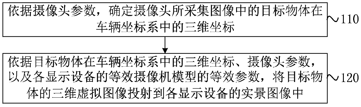
[0029] figure 1 It is a flow chart of an image projection method provided by Embodiment 1 of the present invention. This embodiment is applicable to the situation in which a 3D virtual image corresponding to an actual target object is projected to a display device capable of displaying a real scene in the process of intelligent driving , the method can be performed by an image projection device, which can be implemented in software and / or hardware, and is preferably configured on a display device of an intelligent driving vehicle, such as a central control screen, an instrument panel, a head-up display, and an electronic navigation equipment etc. The method specifically includes the following:
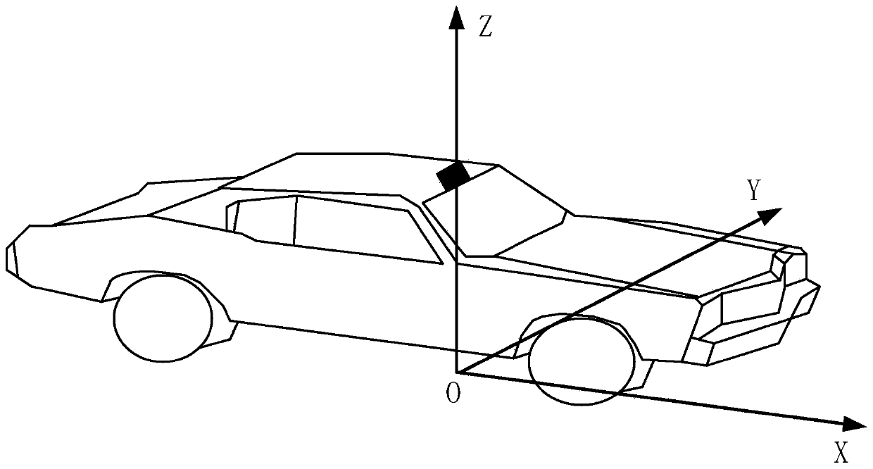
[0030] S110. Determine the three-dimensional coordinates of the target object in the vehicle coordinate system in the image captured by the camera according to the camera parameters.
[0031] In a specific embodiment of the present invention, the three-dimensional virtual image corre...
Embodiment 2
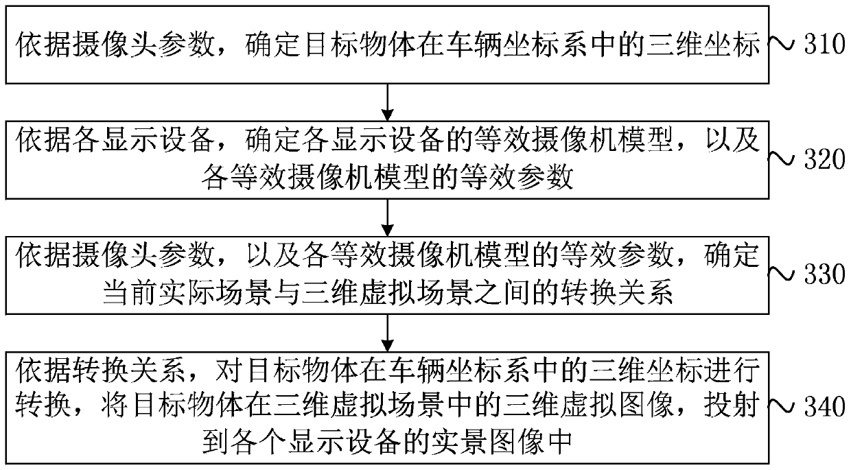
[0040] On the basis of the first embodiment above, this embodiment provides a preferred implementation of the image projection method, which can determine the conversion relationship between the current actual scene and the 3D virtual scene according to the equivalent camera model of the display device. image 3 A flow chart of an image projection method provided by Embodiment 2 of the present invention, such as image 3 As shown, the method includes:
[0041] S310. Determine the three-dimensional coordinates of the target object in the vehicle coordinate system according to the camera parameters.
[0042] In a specific embodiment of the present invention, the target object may be an object obtained from an actual scene, or an object obtained from map data according to vehicle positioning information. Therefore, according to the camera parameters, the three-dimensional coordinates of the target object in the vehicle coordinate system are determined.
[0043] Optionally, iden...
Embodiment 3
[0063] Figure 8 It is a schematic structural diagram of an image projection device provided by Embodiment 3 of the present invention. This embodiment is applicable to projecting a three-dimensional virtual image corresponding to an actual target object to a display device capable of displaying a real scene in the process of intelligent driving , the device can implement the image projection method described in any embodiment of the present invention. Specifically, the device includes:
[0064] The AR object coordinate determining module 810 is used to determine the three-dimensional coordinates of the target object in the vehicle coordinate system in the image collected by the camera according to the camera parameters;
[0065] The AR projection module 820 is configured to project the three-dimensional virtual image of the target object according to the three-dimensional coordinates of the target object in the vehicle coordinate system, the camera parameters, and the equival...
PUM
 Abstract
Description
Claims
Application Information