Assembled modular lamphouse

A modular and light box technology, which is applied in the direction of display devices, instruments, and illuminated signs, can solve the problems of shadowless splicing and box shadows, etc., achieve simple structure, easy installation and maintenance, and improve the astigmatism effect Effect

Inactive Publication Date: 2019-07-02
方迪勇
View PDF12 Cites 2 Cited by
  • Summary
  • Abstract
  • Description
  • Claims
  • Application Information

AI Technical Summary

Problems solved by technology

[0003] For light boxes in the field of advertising communication, there are mainly two structures: one is a light box with a side-entry backlight structure, which is mainly composed of a light guide plate and a light source. The light source is installed on the side of the light guide plate and at the bottom of the light guide plate There are engraved or printed light guide points. Due to the limitation of light guide distance, the light box with side-type backlight structure is suitable for products with a small light-emitting area, such as small-sized decorative paintings, window displays, flat panel lighting, etc. However, There are light sources on both sides or around the light guide plate, so that there are dark areas caused by the light source body on both sides or around the light guide plate, and shadowless splicing cannot be realized
The other is a light box with a direct backlight structure, which is mainly composed of a panel, a light source and a box body. The panel is installed on the front side of the box body, and the

Method used


Image

  • Assembled modular lamphouse
  • Assembled modular lamphouse
  • Assembled modular lamphouse

Examples


Example Embodiment

[0031] The following describes the technical solutions in the embodiments of the present invention clearly and completely in conjunction with the description of the drawings of an assembled modular light box of the present invention.

[0032] The front side and the back side described in the embodiment of the present invention are based on the direction shown in the description of the drawings.

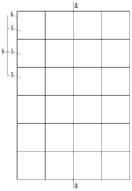
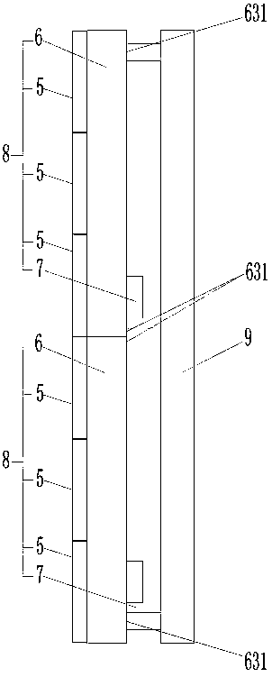
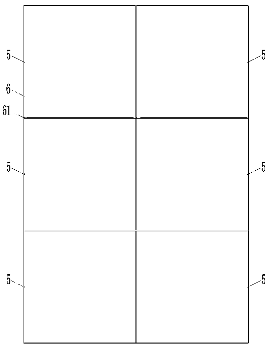
[0033] An embodiment of the assembled modular light box of the present invention. Such as Figure 1 to Figure 5 As shown, the assembled modular light box is composed of a plurality of light-emitting modules 8 assembled in an array. The light-emitting module 8 includes a backlight unit 5, a box body 6 and a power source 7. In addition to the drawings, the light-emitting module 8 can also Including a brightness control system. For a dynamic light box, it also includes a dynamic control system; the box body 6 also includes a box body frame 62 enclosed around the box body mounting surface 61 a...


PUM


Abstract

The invention relates to an assembled modular lamphouse, which is formed by assembling a plurality of light emitting modules according to arrays, wherein each light emitting module comprises back light units, a box body and a power supply; a plurality of back light units are mutually spliced and arranged at a box body installing surface at the front side of the box body according to arrays, and are electrically connected with the power supply; each back light unit consists of an array lamp hole module, a light dispersion surface cover and a light source module; the array lamp hole module is also used for installing the light source module; the light dispersion surface cover is arranged at the front side of an array lens module; a surface cover connecting tongue and groove is in direct insertion connection with a base connecting tongue and groove; the light source module is arranged at the back side of the array lamp hole module, so that the light source at the front side of the light source module is positioned in a lamp hole formed in the base plate, and is fixed by a first screw base post at the back side of the base plate through screws. The assembled modular lamphouse has the advantages that the light emitting is uniform; the structure is simple; the installation and the maintenance are convenient; the requirement of outdoor application is met.

Description

technical field [0001] The invention relates to the field of light boxes, in particular to an assembled modular light box. Background technique [0002] As we all know, light boxes have a wide range of applications, which involve construction, industry, lighting, civil, commercial, medical, advertising, transportation and other special purposes. Among them, the application in the field of advertising communication is the most widely used, mainly including panel light boxes, cloth light boxes, crystal ultra-thin light boxes and plastic ultra-thin light boxes, mirror induction ultra-thin light boxes, magnetic suction ultra-thin light boxes, dynamic light boxes, etc. [0003] For light boxes in the field of advertising communication, there are mainly two structures: one is a light box with a side-entry backlight structure, which is mainly composed of a light guide plate and a light source. The light source is installed on the side of the light guide plate and at the bottom of t...

Claims


Application Information

Patent Timeline
IPC IPC(8): G09F13/04
CPCG09F13/0404G09F13/0409G09F13/0418
Inventor 方迪勇
Owner 方迪勇
Why Eureka
Try Eureka