A light guide plate with a positioning structure and its molding process

A technology of positioning structure and light guide plate, applied in the field of light guide plate, can solve the problems of cumbersome production steps, insufficient uniformity of light guide, inconvenient array connection, etc., and achieves the effects of simple structure, small occupied space and simple manufacturing process

Active Publication Date: 2019-02-01
滁州佳宏光电有限公司
View PDF5 Cites 0 Cited by
  • Summary
  • Abstract
  • Description
  • Claims
  • Application Information

AI Technical Summary

Problems solved by technology

However, most of the existing products adopt the backlight irradiation method, that is, from a certain position (preferably the middle position) of the light guide plate to irradiate the inside, and then use the light transmission function of the light guide plate to transmit to each position. This method has disadvantages, that is, the amount of light guide is not uniform enough. , and the production steps are cumbersome, and it is inconvenient to connect the array, so we propose a molding process of the light guide plate with a positioning structure

Method used


Image

  • A light guide plate with a positioning structure and its molding process

Examples


Embodiment 1

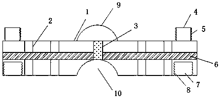
[0017] The present invention provides a light guide plate with a positioning structure, including a light guide plate body 1, a fixing block 9 is provided in the middle of the upper end of the light guide plate body 1, and the middle portion of the lower end of the fixing block 9 is connected to the arc through a limiting hole 3. The upper end of the shaped groove 10, and the fixed block 9 matches the arc groove 10, the upper end of the light guide plate body 1 is provided with light-transmitting blocks 4 on the left and right sides, and the outer side of the light-transmitting block 4 is provided with protrusions 5. The left and right sides of the lower end of the light guide plate body 1 are provided with limiting grooves 7 that match the light-transmitting block 4 , and the inner cavity of the limiting groove 7 is provided with a groove 8 that matches the protrusion 5 . The inner cavity of the light guide plate body 1 is vertically and equidistantly provided with astigmatism...

Embodiment 2

[0024] The present invention provides a light guide plate with a positioning structure, including a light guide plate body 1, a fixing block 9 is provided in the middle of the upper end of the light guide plate body 1, and the middle portion of the lower end of the fixing block 9 is connected to the arc through a limiting hole 3. The upper end of the shaped groove 10, and the fixed block 9 matches the arc groove 10, the upper end of the light guide plate body 1 is provided with light-transmitting blocks 4 on the left and right sides, and the outer side of the light-transmitting block 4 is provided with protrusions 5. The left and right sides of the lower end of the light guide plate body 1 are provided with limiting grooves 7 that match the light-transmitting block 4 , and the inner cavity of the limiting groove 7 is provided with a groove 8 that matches the protrusion 5 . The inner cavity of the light guide plate body 1 is vertically and equidistantly provided with astigmatism...


PUM


Abstract

The invention discloses a light guide plate with a positioning structure. The light guide plate comprises a light guide plate body. The middle of the lower end of a fixed block is connected to the upper end of an arc slot through a limit hole, and the fixed block matches the arc slot. The left and right sides of the upper end of the light guide plate body are provided with transparent blocks. The left and right sides of the lower end of the light guide plate body are provided with limit slots matching the transparent blocks. The cavity of each limit slot is internally provided with a groove matching a bulge. Light dispersion holes are vertically arranged at equal intervals in the cavity of the light guide plate body. A hollow slot vertically intersecting with the light dispersion holes is transversely arranged in the cavity of the light guide plate body. A forming process of the light guide plate with a positioning structure is simple. The effect is more obvious, and maintenance is simple. Compared with the existing light guide plate, the light dispersion effect is improved, the plate takes up a small space, the work efficiency is high, the light color or the light guide plate can be easily changed at any time according to the circumstance, the structure after splicing is simple, and the light guide plate is easy to manufacture and is worth wide use in the future.

Description

technical field [0001] The invention relates to the technical field of light guide plates, in particular to a light guide plate with a positioning structure and a molding process thereof. Background technique [0002] The light guide plate is a product that can transform a line light source into a surface light source. It uses optical-grade acrylic (PMMA) / PC as the base material, and uses backlight module technology to refract the light from the light guide plate into a uniform light state of the surface light source. The product has distinctive features such as ultra-thin, ultra-bright, uniform light guide, energy saving, environmental protection, no dark area, durable, not easy to yellow, simple and quick installation and maintenance, etc., and can be cut into the required size at will, and can also be spliced. The production process is simple and convenient, and the light conversion rate is high at the same time, so it is widely used in LCD screens, advertising light box...

Claims


Application Information

Patent Timeline
Patent Type & Authority Patents(China)
IPC IPC(8): G02B6/00B29C69/02
CPCB29C45/0055G02B6/0051G02B6/0065G02B6/0088
Inventor 孙小会王洪周家义王世昌
Owner 滁州佳宏光电有限公司
Why Eureka
Try Eureka