A transfer structure and a connector comprising the transfer structure

A technology of connectors and main connections, which is applied in the direction of connection, parts of connection devices, contact parts, etc., can solve the problems of error-prone wiring relationships and low production efficiency, and achieve the benefits of wiring arrangement and increasing electrical clearance Effect

Active Publication Date: 2021-01-08
深圳市力为电气有限公司
View PDF7 Cites 0 Cited by
  • Summary
  • Abstract
  • Description
  • Claims
  • Application Information

AI Technical Summary

Problems solved by technology

[0005] The purpose of the present invention is to provide a transfer structure and a connector including the transfer structure, aiming to solve the problems of low production efficiency and error-prone wiring relationship caused by connecting the existing controller and internal components with wires

Method used


Image

  • A transfer structure and a connector comprising the transfer structure
  • A transfer structure and a connector comprising the transfer structure
  • A transfer structure and a connector comprising the transfer structure

Examples


Embodiment 1

[0038] Embodiment 1: Embodiment 1 is a specific implementation of the transfer structure.

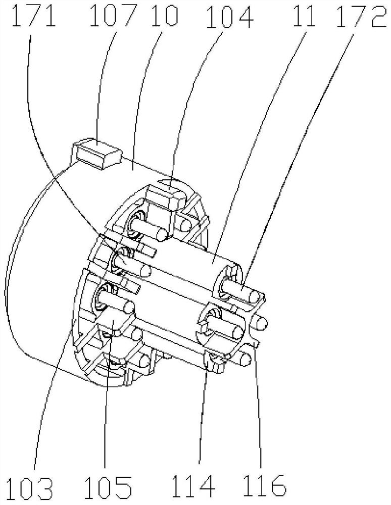
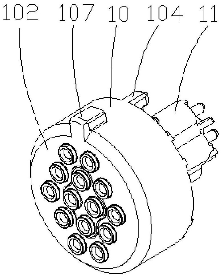
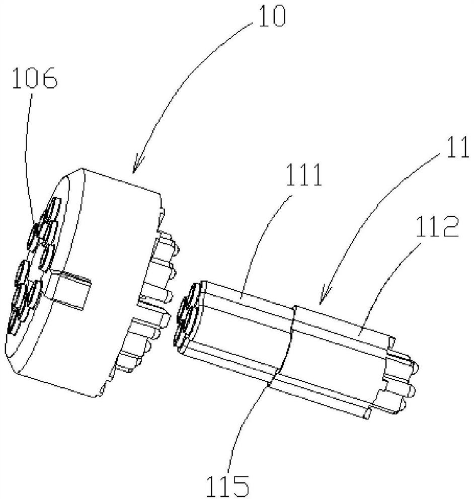
[0039] Such as Figure 1-Figure 10 As shown, a transition structure provided in this embodiment includes a main connector 10, a sub-connector 11, a first receptacle contact 171 and a second receptacle contact 172, and the main connector 10 is provided with a through The socket hole 100 and the first mounting hole 101, the first socket contact 171 is installed in the first mounting hole 101, the sub-connector 11 is provided with a through second mounting hole 110, and the second socket contact 172 is installed In the second mounting hole 110 , the first end of the sub-connector 11 is fitted into the insertion hole 100 for fitting, and the second end of the sub-connection 11 extends out of the insertion hole 100 .

[0040] Such as image 3 , Figure 5 and Figure 6 As shown, the sub-connector 11 includes an insertion portion 111 close to the main connector 10 and an installation porti...

Embodiment 2

[0050] Embodiment 2: Embodiment 2 is a specific implementation of the connector.

[0051] Such as Figure 7 , 11 - Figure 14 As shown, a connector provided in this embodiment includes a socket 14, an insulator 15, an adapter pin 16 and the adapter structure in Embodiment 1. The socket 14 is provided with a through third mounting hole 141, and the insulator 15 is set In the third installation hole 141, the adapter pins 16 are arranged on the insulator 15, the number of the adapter pins 16 is consistent with the sum of the first jack contacts 171 and the second jack contacts 172 and Corresponds to conductive contacts.

[0052] In this embodiment, both ends of the adapter pin 16 are pin-type, one end is mated with the socket, and the other end is mated with the adapter structure.

[0053] Such as Figure 11-Figure 14 As shown, the first end of the main connector 10 is provided with a hollow first protrusion 106 at the outer edge corresponding to the first installation hole ...


PUM


Abstract

The invention provides an adapter structure and a connector including the same. The adapter structure comprises a main connector, a sub-connector, a first socket contact member and a second socket contact member, wherein the main connector is provided with a through insertion hole and a through first mounting hole; the first socket contact member is installed in the first mounting hole; the sub-connector is provided with a through second mounting hole; the second socket contact member is installed in the second mounting hole; the first end of the sub-connector is embedded in the insertion hole; and the second end of the sub-connector extends out of the insertion hole. The main connector and the sub-connector are nested to form the split-type adapter structure. The first socket contact member extends out of the first mounting hole end and is soldered to a line on a main printed board inside the controller. The second socket contact member extends out of the second mounting hole end to be soldered to a line on a sub-printed board inside the controller. Thus, a purpose of replacing the wires of internal components of the controller with a printed circuit can be well achieved.

Description

technical field [0001] The invention relates to the technical field of smart grid connection equipment, in particular to a transfer structure and a connector including the transfer structure. Background technique [0002] Smart grid can effectively solve many energy and environmental problems in modern society, and achieve long-term sustainable economic and social development. [0003] In recent years, with the transformation and upgrading of domestic smart grids, the application of smart switches and corresponding controllers for smart grid private network transformation has become more and more popular. In the latest national grid standards, aviation connectors are used for electrical and signal connections between the controller and the smart switch. [0004] The existing controllers use cup welding wire type aviation connectors to connect with internal components. This connection method has complex wiring relationships, and the wiring relationships are prone to errors d...

Claims


Application Information

Patent Timeline
Patent Type & Authority Patents(China)
IPC IPC(8): H01R13/506H01R31/06H01R13/04H01R13/10
CPCH01R13/04H01R13/10H01R13/506H01R31/06
Inventor 谢郴恒
Owner 深圳市力为电气有限公司
Why Eureka
Try Eureka