Suspension assembly having recessed actuator with simplified lead connection

a technology of recessed actuators and lead connections, which is applied in the direction of magnetic recording, data recording, instruments, etc., can solve the problems of tack soldering connections, excessively delicate manual operations to weave, fixture, and tack soldering connections, etc., to facilitate routing the trace, improve reliability, and increase the effect of packing density

Active Publication Date: 2010-07-06
MAGNECOMP
View PDF14 Cites 56 Cited by
  • Summary
  • Abstract
  • Description
  • Claims
  • Application Information

AI Technical Summary

Benefits of technology

[0012]A further advantage of the invention enabled by grounding the microactuator to a raised bottom portion of a baseplate or load beam is the ability to position the microactuator such that its lead connection surface is closest to the slider. This facilitates routing the trace from the microactuator lead connection to the read / write head. Other advantages of a suspension assembly equipped with a microactuator according to the invention include better reliability through elimination of mechanical hinges and stiffeners, greater packing density, minimal tail weaving, fewer fabrication steps, less expensive manufacturing, higher structural gain amplification, higher sway mode and shock resistance, no dimple friction, less windage, and the ability to position the actuator closer to the gimbal.
[0013]Related systems, methods, features and advantages of the invention or combinations of the foregoing will be or will become apparent to one with skill in the art upon examination of the following figures and detailed description. It is intended that all such additional systems, methods, features, advantages and combinations be included within this description, be within the scope of the invention, and be protected by the accompanying claims.

Problems solved by technology

In general, in all of the suspension assemblies described in the foregoing patents, the coupling of a hinge to the piezo actuator adds to the manufacturing complexity.
Effecting multiple piezo lead connections can be troubling, and in any case burden the manufacturing process with additional steps.
These techniques entail excessive delicate manual operations to weave, fixture, and tack solder the connections.
This arrangement requires an FOS having an extended tail portion woven to a soldering location on the upper surface of the piezo, and causes manufacturing difficulties: extended tail weaving in this fashion undesirably reduces assembly packing density; installing solder bumps on the flexure adds significant fabrication cost; and the thermal soldering operation itself can degrade piezo performance as it often exceeds the Curie temperature of the actuator.
Dual actuator designs cause performance tradeoffs as well.
However, inclusion of a hinge or a second actuator into the suspension tends to degrade its frequency response.
This is typically a result of weak coupling properties of the piezo-hinge structure at both the front and distal ends of the suspension.
In some prior art, stiffeners are provided to strengthen the coupling of the distal end, but this adversely affects actuator performance by reducing the attainable stroke levels.
Stiffeners also introduce windage-induced turbulence on the head, due to their geometric features being out of plane.
But these techniques concentrate more stress on the hinges, leading to early fatigue and material failure.

Method used


Image

  • Suspension assembly having recessed actuator with simplified lead connection
  • Suspension assembly having recessed actuator with simplified lead connection
  • Suspension assembly having recessed actuator with simplified lead connection

Examples


Embodiment Construction

[0036]In accordance with the objectives of the invention set forth above, preferred embodiments are now described in further detail, which, when read in conjunction with the claims and drawings, give broader meaning and scope to the spirit of the invention.

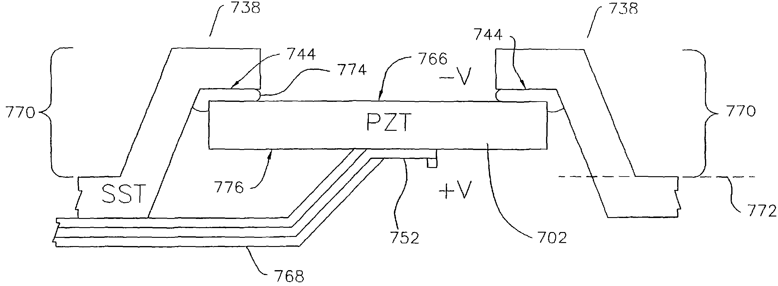
[0037]As utilized herein, the term “piezo” means any piezoelectric material, including piezoceramics, piezotransducers (PZT) and all other compounds that exhibit the piezoelectric effect.

[0038]As utilized herein, terms such as “about” and “substantially” and “approximately” are intended to allow some leeway in mathematical exactness to account for tolerances that are acceptable in the trade, or that would otherwise encompass a functionally equivalent variation. Accordingly, any deviations upward or downward from any value modified by such terms should be considered to be explicitly within the scope of the stated value.

[0039]The present invention discloses a piezo microactuator for rotational actuation of loads on HDD head suspensi...


PUM

PropertyMeasurementUnit
voltageaaaaaaaaaa
areaaaaaaaaaaa
recessed areaaaaaaaaaaa

Abstract

A head suspension assembly couples a baseplate to a rotatable load through a planar triangular piezo microactuator for effecting hingeless rotation of the load. The microactuator expands, responsive to an excitation voltage, with greater magnitude in one direction than in another direction normal to the first direction, resulting in an angular movement of the hypotenuse thereby rotating the load. The upper surface of the microactuator is grounded to a bottom surface of the baseplate or load beam to position the microactuator lead connection surface closest to the load to facilitate trace routing. A load beam grounding surface may be raised to accommodate the microactuator and fix the lead connection surface on a common plane with the unraised surface to further minimize trace routing and provide access for bonding the trace to the load beam.

Description

CROSS-REFERENCE TO RELATED APPLICATION[0001]This is a continuation of application Ser. No. 11 / 282,305, filed Nov. 18, 2005 now U.S. Pat. No. 7,595,965. The entire contents of this application are hereby incorporated by reference.BACKGROUND[0002]1. Field of the Invention[0003]The present invention relates generally to suspension systems for hard disk drive systems. More specifically, the present invention relates to piezoelectric micro-actuators for hingeless actuation of loads in hard disk drive head suspension assemblies.[0004]2. Related Art[0005]Microactuators have many applications. For example, in the magnetic disk drive industry, piezoelectric (hereinafter “piezo”) microactuators have become an attractive alternative to voice coil actuators, particularly in high-density applications. As industry trends have demanded higher density storage capabilities, piezo actuators have been more frequently employed in HDD systems because they allow for more precise radial positioning of the...

Claims


Application Information

Patent Timeline
Patent Type & Authority Patents(United States)
IPC IPC(8): G11B5/48
CPCG11B5/5552G11B5/4873
Inventor KULANGARA, SIVADASAN K.MEI, SHIJINMISUTA, STEVESCHREIBER, CHRISTOPHER
Owner MAGNECOMP
Why Eureka
Try Eureka