
Routing engine for telecommunications network

a routing engine and telecommunications network technology, applied in the field of telecommunications network routing engine, can solve the problems of many dead ends, many manual processes, and many complicated steps, and achieve the effect of reducing the number of manual processes

Active Publication Date: 2006-12-05
LEVEL 3 COMM LLC
View PDF33 Cites 54 Cited by
  • Summary
  • Abstract
  • Description
  • Claims
  • Application Information

AI Technical Summary

Benefits of technology

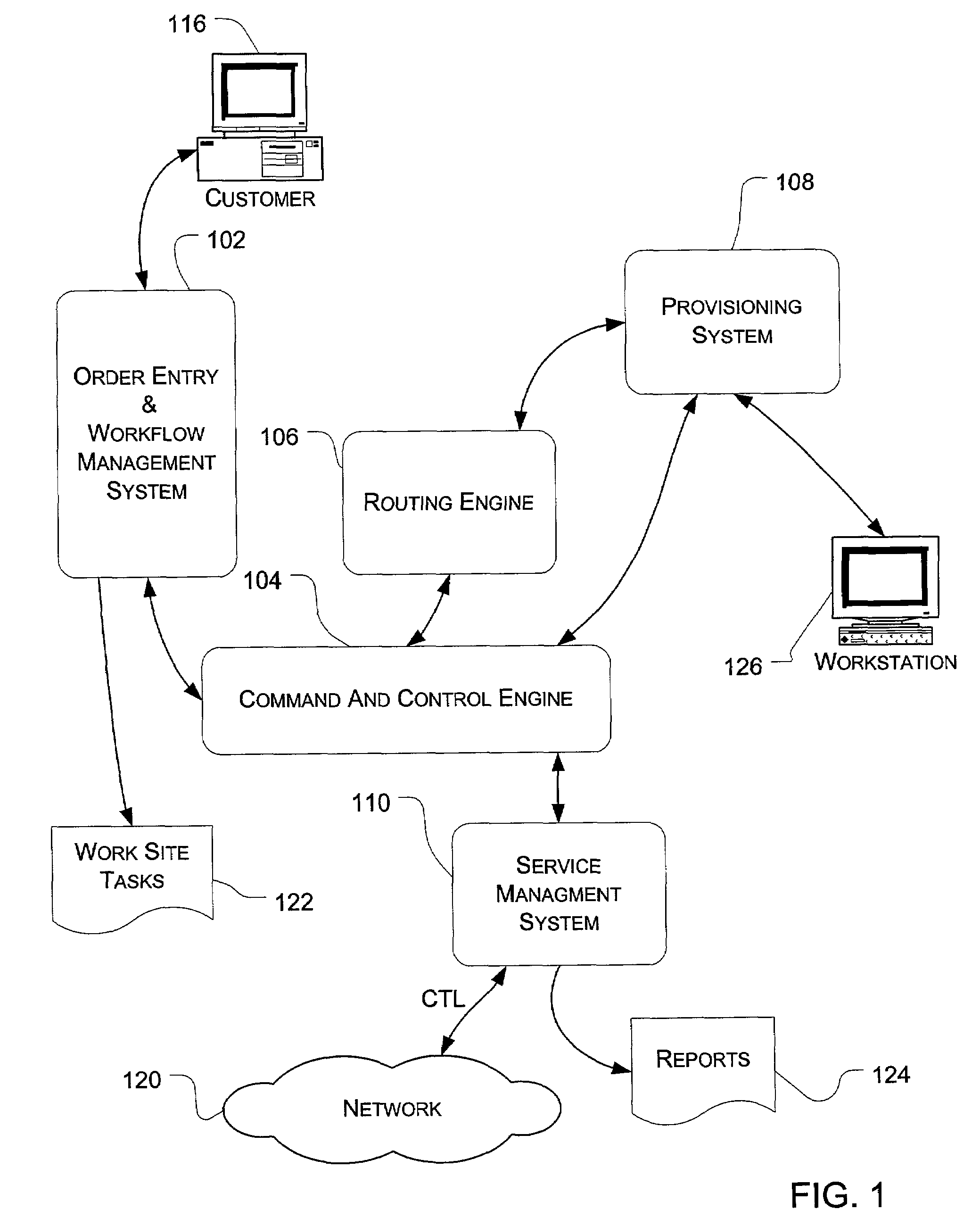
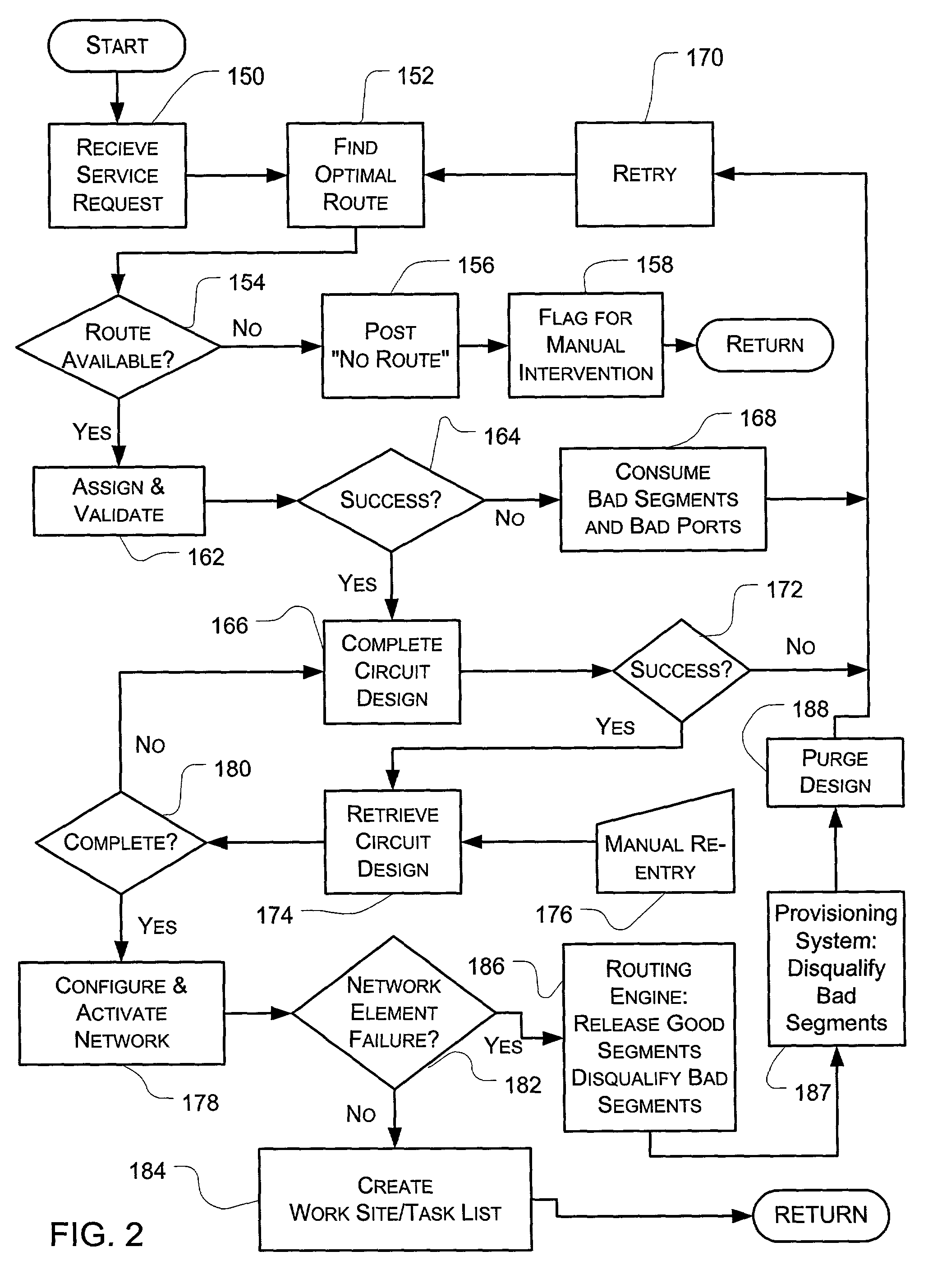
[0005]In accordance with the present invention, the above and other problems are solved by automating the design process for designing an optimal route for a private line circuit between a source and a destination location, as specified in a communication line installation request. Based on the current available capacity between the source location and the destination location, a routing engine automates the design of a least cost route for the private line circuit through a communications network. The routing engine then provides details of the route to a system managing the installation of the private line circuit.
[0009]The great utility of the invention is that an optimal route for a circuit may be designed within a matter of seconds, rather than months. Additionally, the automated process guarantees that each route designed for a particular telecommunications carrier is designed in substantially similar fashion, thereby eliminating design inconsistencies associated with prior manual processes administered by any number of route designers.

Problems solved by technology

Routing a communication line for a telecommunications network is a manual process involving many complicated steps.
This may be a least cost route on the given network or this route may incur more cost than is necessary.
The designer may run into many dead ends when designing a manual route because the route has many directions it may branch along the way.
These directions may or may not have capacity links available to get the circuit from source to destination.
This process may take much time and could yield a good to mediocre route.
Furthermore, no assurances can be made to the customer until the above analysis is complete.
Such a delay is not only a burden to the customer, but may cost the network provider the contract.

Method used


Image

  • Routing engine for telecommunications network
  • Routing engine for telecommunications network
  • Routing engine for telecommunications network

Examples


Embodiment Construction

[0019]The logical operations of the various embodiments of the present invention are implemented (1) as a sequence of computer implemented steps or program modules running on a computing system and / or (2) as interconnected machine logic circuits or circuit modules within the computing system. The implementation is a matter of choice dependent on the performance requirements of the computing system implementing the invention. Accordingly, the logical operations making up the embodiments of the present invention described herein are referred to variously as operations, structural devices, acts or modules. It will be recognized by one skilled in the art that these operations, structural devices, acts and modules may be implemented in software, in firmware, in special purpose digital logic, and any combination thereof without deviating from the spirit and scope of the present invention as recited within the claims attached hereto.

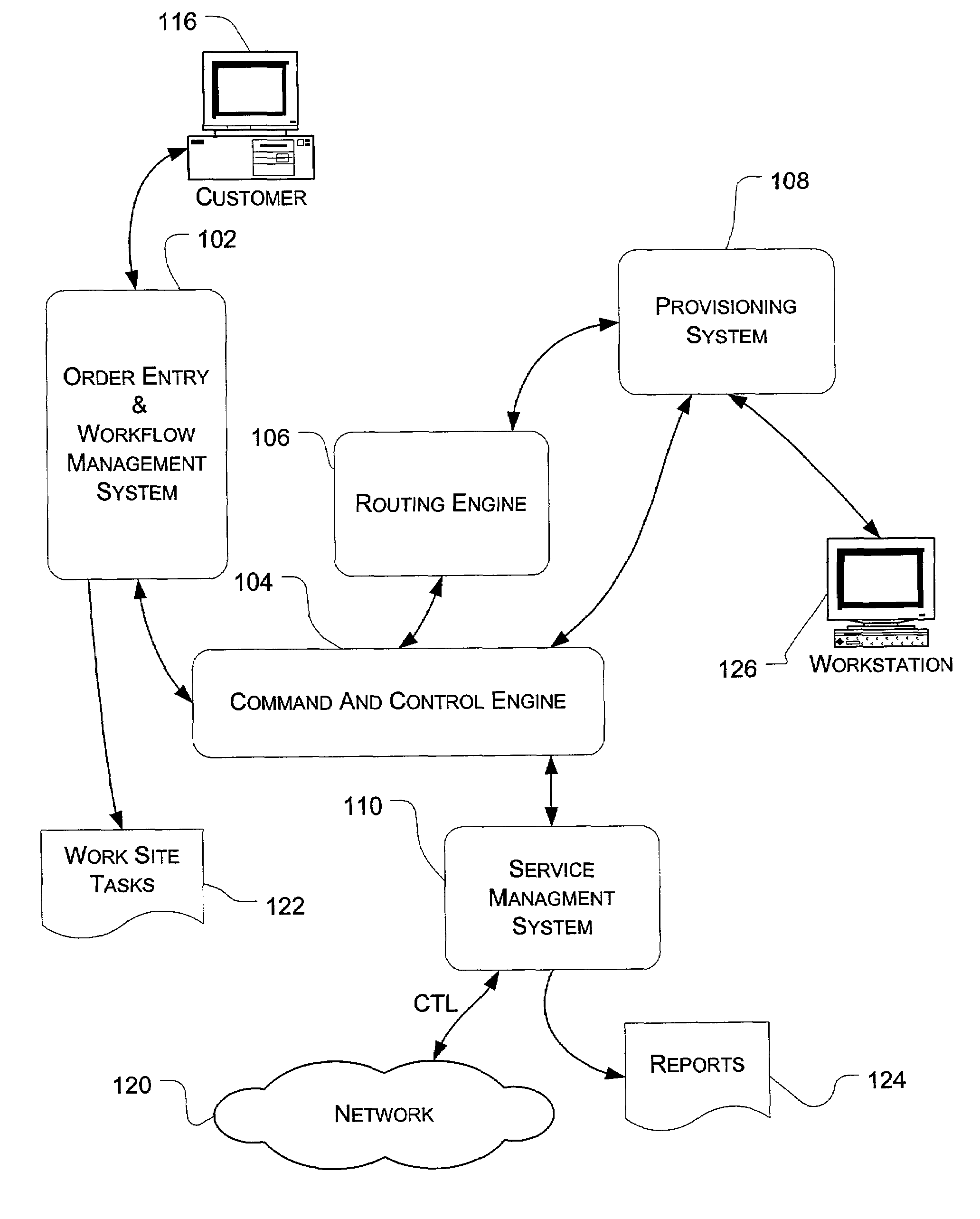
[0020]FIG. 1 shows the architecture of an automated insta...


PUM


Abstract

A system for automated installation of a communication line using an optimal route between a source location and a destination location is disclosed. The system includes a routing engine providing an automated design process for rendering the optimal route. The routing engine utilizes a routing algorithm to select the optimal route from a graph of capacity links defining a plurality of possible routes between the source and destination locations. If, at any time during the design process, the optimal route or capacity links defining the optimal route are detected as unavailable for any reason, the routing engine re-initiates the design process and thereafter selects a new optimal route based upon a new capacity graph built without the previously unavailable capacity link. Once designed, the available optimal route is provided to a command and control engine, which, in turn, manages the installation of the communication line using the optimal route. The command and control engine manages the process for assigning the optimal route in the provisioning system.

Description

CROSS REFERENCE TO RELATED APPLICATIONS[0001]This application is related to subject matter disclosed in U.S. patent application for an AUTOMATED INSTALLATION OF NETWORK SERVICE IN A TELECOMMUNICATIONS NETWORK, Ser. No. 10 / 057,041, filed concurrently herewith, the subject matter of which is incorporated in this application by reference.TECHNICAL FIELD[0002]This invention relates to a routing engine for a telecommunications network. More particularly, this invention relates to finding an optimal route from source to destination including connections at the source, destination, and all intermediate locations.BACKGROUND OF THE INVENTION[0003]Routing a communication line for a telecommunications network is a manual process involving many complicated steps. After a customer's service request for a communication line is received by a telecommunications company that is hired to install the line, the design process begins. First, a designer selects a path that he\she deems the best path to a...

Claims


Application Information

Patent Timeline
IPC IPC(8): H04M7/00H04L12/28H04L12/721H04L12/725
CPCH04L45/12H04L45/302
Inventor HOLLMAN, BRETT P.MARTIN, JEFFREY L.JOSEPH, GEORGE T.HENES, ALEX J.BONEWITZ, CHRISTOPHER M.ASALIAN, KAVEHYAWORSKI, GEOFF R.RYCZEK, GARY L.TRAIN, COLIN G.
Owner LEVEL 3 COMM LLC
Learn More