
Forming a sacrificial layer in order to realise a suspended element

a technology of sacrificial layer and element, which is applied in the direction of variable capacitor, capacitor with electrode distance variation, electrical apparatus, etc., can solve the problems of non-photosensitive polymers that are difficult to implement, non-photosensitive polymers and non-organic materials that require suitable etching techniques, and expensive polishing steps (cmp). to achieve the effect of simplifying the method of realisation

Inactive Publication Date: 2008-04-17
COMMISSARIAT A LENERGIE ATOMIQUE ET AUX ENERGIES ALTERNATIVES
View PDF1 Cites 6 Cited by
  • Summary
  • Abstract
  • Description
  • Claims
  • Application Information

AI Technical Summary

Benefits of technology

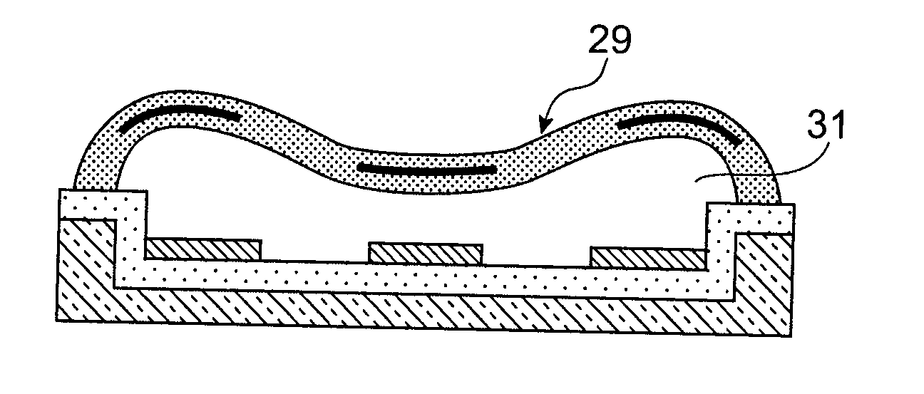
[0022] This invention was designed in order to form the sacrificial layer while simplifying its method of realisation. It makes it possible to planarise a sacrificial layer. It also makes it possible to realise a “double air gap” variable capacitor at least cost.
[0032] a thinning step of the first pattern element in order to minimise the surface topology of said zone reproduced at the first pattern element,
[0038] a thinning step of the first pattern element in order to minimise the surface topology of said zone reproduced at the surface of the first pattern element,

Problems solved by technology

Non-photosensitive polymers are difficult to implement and require the use of another material above them which is photosensitive or which reproduces the patterns to be etched, in order to be etched.
In order to have a non-organic planar sacrificial layer, an expensive polishing step (CMP) is required.
Furthermore, non-photosensitive polymers and non-organic materials require suitable etching techniques and are generally harder to manipulate and to remove during releasing, leaving residue.
Photosensitive polymers used in known art are also not very planarising.
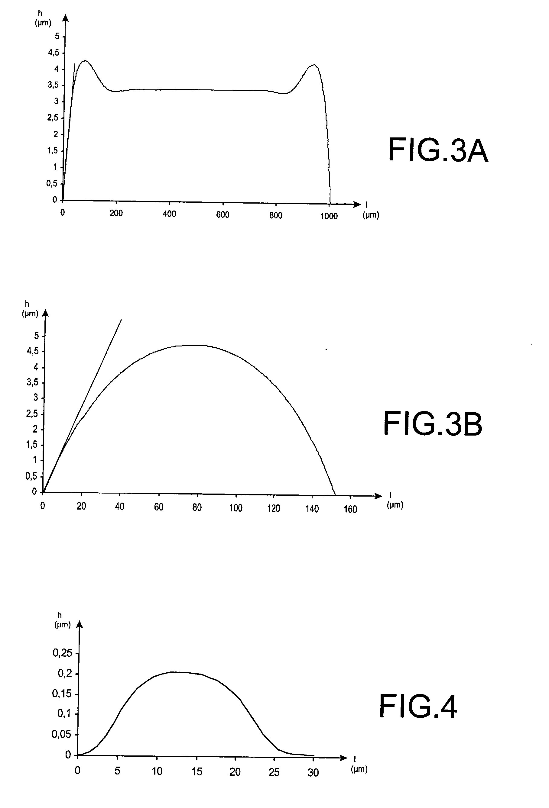
The profile obtained has a pit which can be problematic in certain cases (compression membrane).
But it has the problem referred to as “pull-in” (gluing of the electrodes to ⅓ of the gap).

Method used


Image

  • Forming a sacrificial layer in order to realise a suspended element
  • Forming a sacrificial layer in order to realise a suspended element
  • Forming a sacrificial layer in order to realise a suspended element

Examples


Embodiment Construction

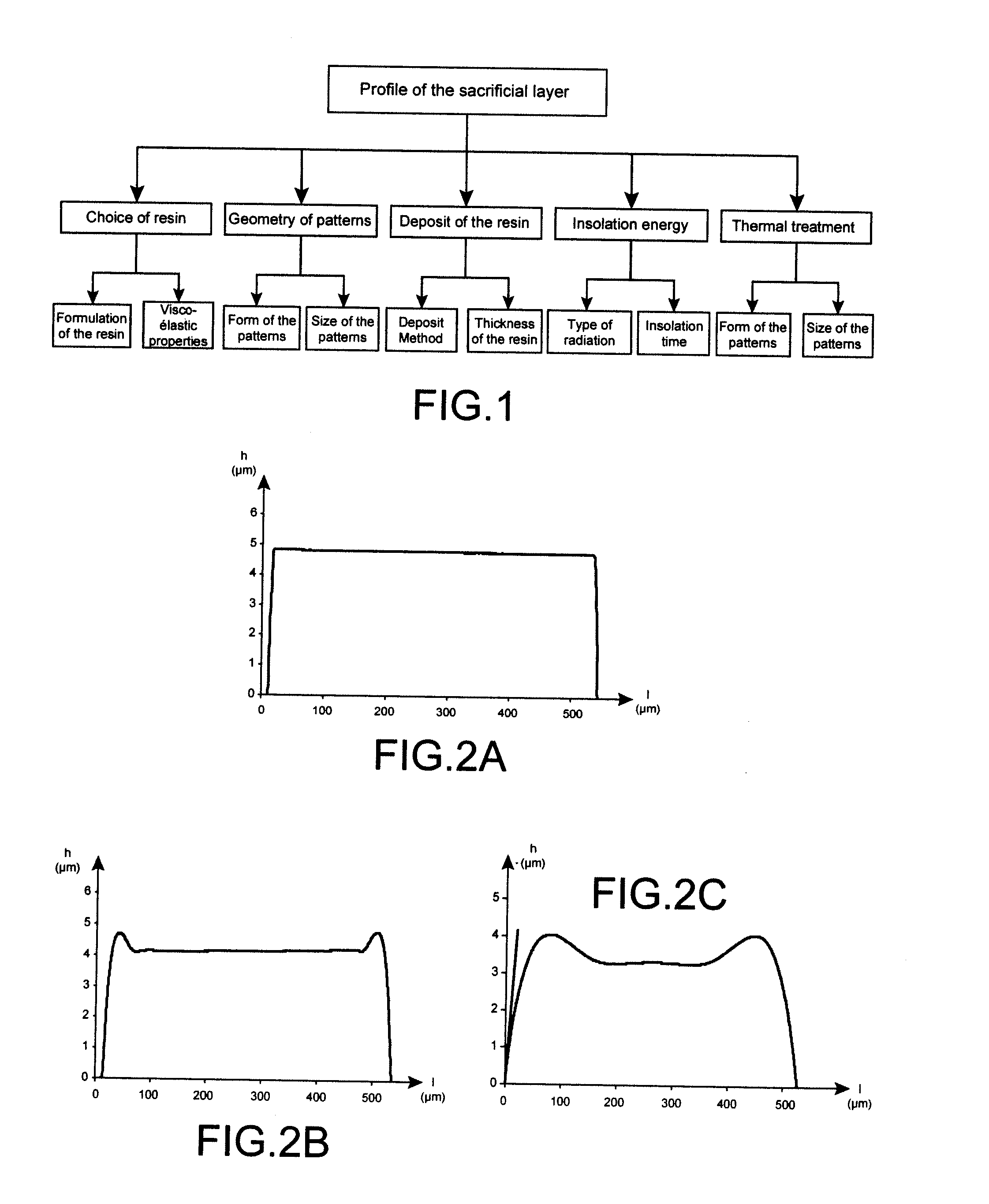
[0053] Several parameters can influence the final aspect of the sacrificial layer, in particular the manner of depositing the photosensitive polymer resin, the type of polymer, its viscosity, its adhesion capacity, the thermal treatment subsequent to the deposition, solvents used during dilution, the atmospheric conditions (temperature and humidity) and storage conditions.

[0054] In order to understand how these parameters change, the sequences of implementing this sacrificial layer must be known. The method of realisation of a suspended element includes the steps of depositing the resin, and of annealing (for example towards 90° C.) in order to give strength to the resin, insolation of the resin, revelation or development of the resin, of the thermal cycle which continues via the deposition of the suspended element and the etching of openings in order to obtain access to the sacrificial layer and its removal.

[0055] Optimising the profile of the sacrificial layer corresponds to opt...


PUM


Abstract

The invention relates to a method of realization of a sacrificial layer, including the steps of: lithography of a resin deposited on a substrate in order to supply a lithographed resist pattern on a substrate zone, the zone having a given size and a given form, the pattern occupying a given volume, annealed according to a thermal cycle of the lithographed resist pattern, the method being characterised in that it includes, according to the resin, the determination of the size and of the form of said zone of the substrate, and the determination of the volume of the resin deposited on said zone so that the thermal cycle annealing supplies a profile chosen from among the following profiles: a planarising domed profile and a “double air gap” profile.

Description

TECHNICAL FIELD [0001] The invention relates to a method of forming a sacrificial layer in order to realize a suspended element (beam or membrane) especially in an MEMS. It can also apply to other fields in electronics and microelectronics that use variable capacitors, switches and resonators. PRIOR ART [0002] The development of smaller and smaller high-performance portable devices encourages the search for new components in order to realize new functionality. In radiofrequency applications, microelectromechanical systems (MEMS) are credible alternatives to “traditional” components in microelectronics through their integration and their theoretical performance. [0003] The operating principle of MEMS is based on the mechanical movement of a membrane or of a beam suspended above a substrate. For this, the MEMS development often requires the use of a sacrificial layer allowing an element (beam or membrane) to be suspended so that it is mobile or isolated from the substrate. [0004] As w...

Claims


Application Information

Patent Timeline
Patent Type & Authority Applications(United States)
IPC IPC(8): H01L21/311
CPCB81B2203/0109B81C1/00103H01G5/18B81C2201/0108H01G5/011B81C1/00158
Inventor CASSET, FABRICESOULIMANE, SOFIANE
Owner COMMISSARIAT A LENERGIE ATOMIQUE ET AUX ENERGIES ALTERNATIVES
Learn More