Controlling power supply to vehicles through a series of electrical outlets

a technology of electrical outlets and power supply, applied in the direction of electric devices, process and machine control, instruments, etc., can solve the problems of increasing operational costs, imposing many inherent restrictions and limitations, and central contactor controls carrying substantial installation and maintenance costs, so as to achieve the effect of reducing costs

Active Publication Date: 2011-08-18
ROSENDAHL GLENN
View PDF7 Cites 7 Cited by
  • Summary
  • Abstract
  • Description
  • Claims
  • Application Information

AI Technical Summary

Benefits of technology

[0135]Preferably the hours are selected on the basis of least cost to the device user.

Problems solved by technology

Energy costs and conservation efforts have led to the widespread use of parking lot controls.
Many inherent restrictions and limitations are imposed by this form of centralized control.
Central contactor controls carry substantial installation and maintenance costs, with typical installation pay back periods in the order of five years or more.
The longevity of mechanical contactors depend heavily on regular maintenance adding to operational costs.
But since no adequate means of enforcement exists, it is left open to abuse.
Often enough users abuse the set limits to trip the main breaker for a lot, inconveniencing all patrons.
In addition, individual parking stall breakers are tripped due to temporary short circuits, overloads, etc.
Since no feedback as to the presence of power is provided for users or maintenance personnel, this stall maybe without power for several days.

Method used


Image

  • Controlling power supply to vehicles through a  series of electrical outlets
  • Controlling power supply to vehicles through a  series of electrical outlets
  • Controlling power supply to vehicles through a  series of electrical outlets

Examples


Embodiment Construction

[0146]The following description is taken from the above patent of the present inventor, the complete disclosure of which is incorporated herein by reference, to describe the context of the present invention.

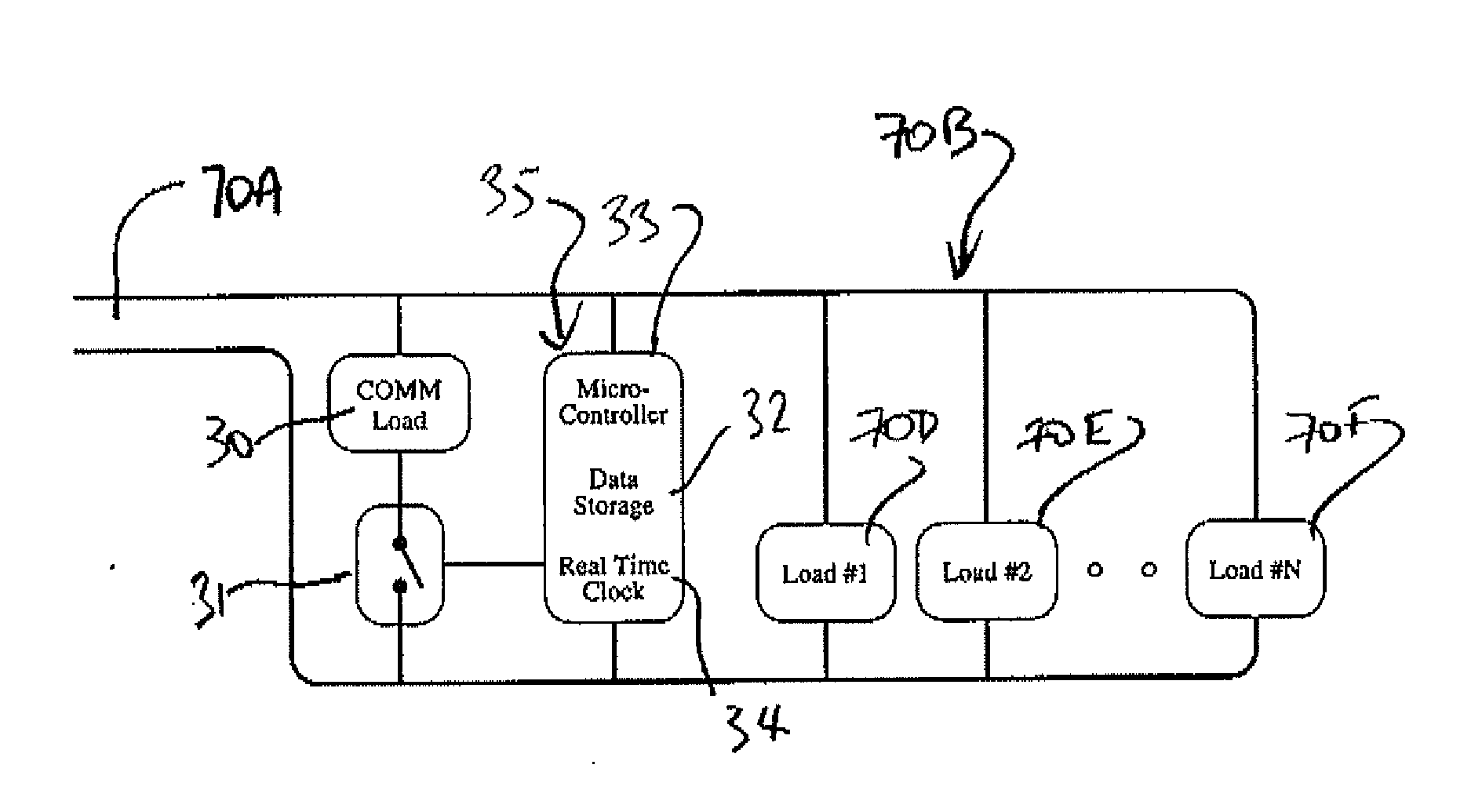
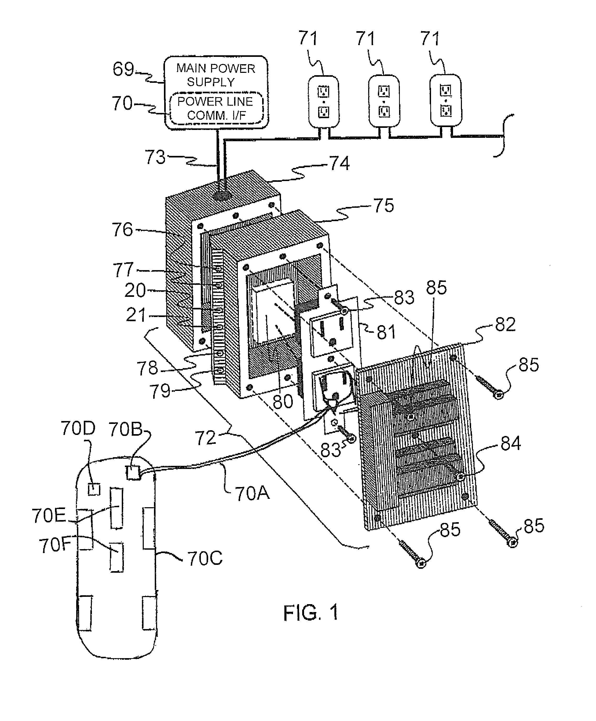
[0147]In FIG. 1 is shown an overview of the whole system which includes a main power supply 69 for supplying electrical power to a plurality of outlets 71, most of which are shown only schematically but one of which indicated at 72 is shown in an exploded isometric view. The electrical power is supplied through wiring 73 which is again shown only schematically without distinguishing between the hot, neutral or ground wires.

[0148]The main power supply comprises basically only a main breaker and possibly a number of subsidiary breakers to a number of different circuits depending upon the number of outlets to be supplied.

[0149]It is a conventional practice to provide the outlet as paired outlets with each pair within a separate receptacle mounted at a spaced position around the car ...


PUM


Abstract

A system for supplying electrical power to a plurality of vehicles from a central power supply through a plurality of electrical outlets includes an outlet control unit for each of the outlets and a vehicle control unit for each of the vehicles. The outlet microprocessor switches the supply of power to the outlet to communicate data to the vehicle. The vehicle microprocessor communicates data by switching a load across the power supply to provide interaction between the microprocessors to manage requirement and availability of power. The data includes whether the power plant of the vehicle is gasoline powered, diesel powered, hybrid or electric battery powered. The microprocessor of the vehicle control unit is arranged to control switches which supply power to selected loads in the vehicle and includes an interface which is arranged to connect to a Canbus communication system of the vehicle.

Description

[0001]This invention relates to an apparatus for supplying electrical power to a number of vehicles through separate electrical outlets.BACKGROUND OF THE INVENTION[0002]In colder regions of the globe electrical devices are used to heat automobile engines and interiors to facilitate engine starting and user comfort. Energy costs and conservation efforts have led to the widespread use of parking lot controls. These controls are designed to reduce energy consumption while still satisfying engine starting and user comfort constraints. Numerous algorithms have been devised to limit this consumption, ranging from simple timers to the most current proportional temperature controls (the colder it gets the more power is delivered).[0003]Current parking lot controls are centralized, whereby all the loads of a parking lot are switched together on or off by a central contactor. Many inherent restrictions and limitations are imposed by this form of centralized control. Central contactor controls...

Claims


Application Information

Patent Timeline
Patent Type & Authority Applications(United States)
IPC IPC(8): G06F17/00
CPCB60L1/04H02J3/14Y04S20/222Y02B70/3225Y02T90/16H02J2310/58
Inventor ROSENDAHL, GLENN
Owner ROSENDAHL GLENN
Why Eureka
Try Eureka