
Hole punching machine with guiding column

A punching machine and guide column technology, which is applied to machine tools designed for grinding the rotating surface of workpieces, manufacturing tools, and parts of grinding machine tools, etc., can solve the problems of time-consuming and labor-intensive, achieve good stamping effect, reduce The effect of small wear and reduced contact area

Inactive Publication Date: 2019-07-05
JIANGSU A KERR BIOLOGICAL RECOGNITION TECH CO LTD
View PDF7 Cites 0 Cited by
  • Summary
  • Abstract
  • Description
  • Claims
  • Application Information

AI Technical Summary

Problems solved by technology

[0002] In the smartphone fingerprint chip processing process, it is necessary to code the back of the processed chip product. In the existing process, it is generally necessary to remove each chip product from the processing carrier board, and then turn it over and place it on another chip product for coding. It takes a lot of time and labor to carry out the coding operation on the carrier board. In view of the above problems, a punching machine with guide posts is now provided to punch the processing carrier board, so that the area where the chip product needs to be coded is hollowed out. It is only necessary to directly turn over the processing carrier board for coding operation, which greatly saves manpower

Method used


Image

  • Hole punching machine with guiding column
  • Hole punching machine with guiding column
  • Hole punching machine with guiding column

Examples


Embodiment 1

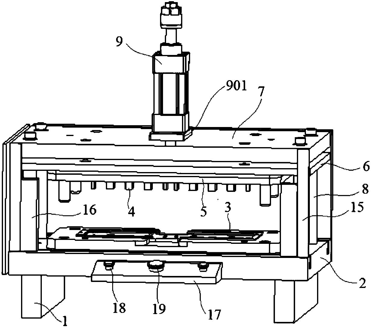
[0037] Embodiment 1: A punching machine with guide posts, including a base 1, a base plate 2, a carrier plate 3, a pressing plate 5 with a punching head 4, a movable plate 6 and a fixed plate 7, and the base plate 2 is installed on the base 1 On the surface, the carrier plate 3 is arranged on the upper surface of the base plate 2, and the base plate 2 and the fixed plate 7 are fixedly connected by at least two guide posts 8. The upper surface of the fixed plate 7 has a cylinder 9, and the cylinder 9 The piston rod passes through the fixed plate 7 and is fixedly connected with the movable plate 6 below the fixed plate 7, the pressing plate 5 is installed on the lower surface of the movable plate 6, and the stamping head 4 is evenly arranged on the lower surface of the pressing plate 5;

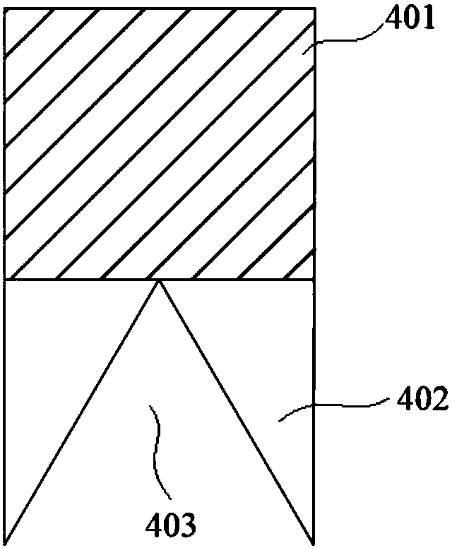
[0038] The punch 4 is composed of a body part 401 and a punch part 402, the upper surface of the body part 401 is connected to the lower surface of the pressing plate 5, and a V-shaped groove 40...

Embodiment 2

[0049] Embodiment 2: A punching machine with guide posts, including a base 1, a base plate 2, a carrier plate 3, a pressing plate 5 with a punching head 4, a movable plate 6 and a fixed plate 7, and the base plate 2 is installed on the base 1 On the surface, the carrier plate 3 is arranged on the upper surface of the base plate 2, and the base plate 2 and the fixed plate 7 are fixedly connected by at least two guide posts 8. The upper surface of the fixed plate 7 has a cylinder 9, and the cylinder 9 The piston rod passes through the fixed plate 7 and is fixedly connected with the movable plate 6 below the fixed plate 7, the pressing plate 5 is installed on the lower surface of the movable plate 6, and the stamping head 4 is evenly arranged on the lower surface of the pressing plate 5;

[0050] The punch 4 is composed of a body part 401 and a punch part 402, the upper surface of the body part 401 is connected to the lower surface of the pressing plate 5, and a V-shaped groove 40...


PUM


Abstract

The invention discloses a hole punching machine with a guiding column. The hole punching machine comprises a base, a base plate, a carrier plate, a pressing plate with a punching head, a moving plateand a fixing plate, the base plate is installed on the upper surface of the base, the upper surface of the fixing plate is provided with an air cylinder, a piston rod of the air cylinder penetrates through the fixing plate to be fixedly connected with the moving plate located below the fixing plate, the pressing plate is installed on the lower surface of the moving plate, the guiding column penetrates through a through hole, a bearing is arranged between the outer side surface of the guiding column and the inner wall of the through hole, each of the two ends of the front side of the base is provided with a connecting column, each of the inner sides of the connecting columns is fixedly provided with an alarming device, an operation table is arranged, and two starting buttons and one emergency stopping button are arranged on the operation table. According to the hole punching machine, a sharp corner part is formed on each of the two sides of the rear end of a punching head through the V-shaped groove arrangement of the punching head part to allow the contacting area of a to-be-punched carrier plate membrane to be greatly reduced to ensure the punching pressure, a better punching effect is achieved, and fringed edges of punched holes can be effectively prevented.

Description

technical field [0001] The invention relates to a device testing device, in particular to a punching machine with a guide post. Background technique [0002] In the smartphone fingerprint chip processing process, it is necessary to code the back of the processed chip product. In the existing process, it is generally necessary to remove each chip product from the processing carrier board, and then turn it over and place it on another chip product for coding. It takes a lot of time and labor to carry out the coding operation on the carrier board. In view of the above problems, a punching machine with guide posts is now provided to punch the processing carrier board, so that the area where the chip product needs to be coded is hollowed out. It is only necessary to directly turn over the processing carrier board for coding operation, which greatly saves manpower. Contents of the invention [0003] The object of the present invention is to provide a punching machine with a gui...

Claims


Application Information

Patent Timeline
Patent Type & Authority Applications(China)
IPC IPC(8): B26F1/02B26F1/14B26D7/22B26D7/00B24B41/00B24B41/06B24B5/04B24B5/08
CPCB24B5/04B24B5/08B24B41/005B24B41/06B26D7/0006B26D7/22B26F1/02B26F1/14
Inventor 陈东王海昌陈松姚燕杰王凯姜海光
Owner JIANGSU A KERR BIOLOGICAL RECOGNITION TECH CO LTD
Learn More