
Computerized embroidery machine thread combing structure

An embroidery machine and thread combing technology, applied in the field of computerized embroidery machine combing thread structure, can solve problems such as failure to comb thread ends or joints in time, joints or thread ends stuck in knitting parts, affecting embroidery quality, etc., so as to improve embroidery weaving quality. , prevent running lines, use flexible effects

Inactive Publication Date: 2019-07-05
SHAOXING KEQIAO TONGYI SCI & TECH INFORMATION CONSULTING CO LTD
View PDF0 Cites 0 Cited by
  • Summary
  • Abstract
  • Description
  • Claims
  • Application Information

AI Technical Summary

Problems solved by technology

[0002] The embroidery machines currently on the market that use computer control to embroider and weave are prone to thread jams during the embroidery weaving process. This is because there will be some thread joints in the lines, and the thread ends or joints are not combed in time, which will lead to joints or thread ends during weaving and embroidery. Stuck in the woven parts, affecting the overall embroidery quality, and currently lacks related structures, which need to be improved

Method used

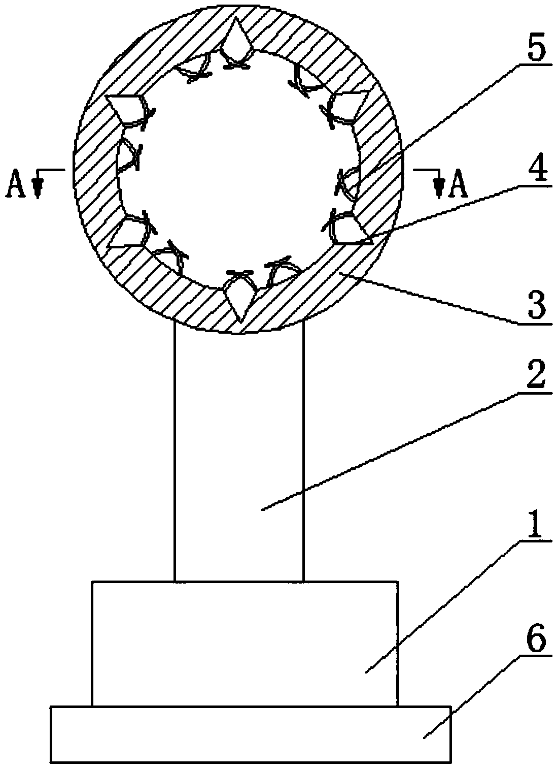
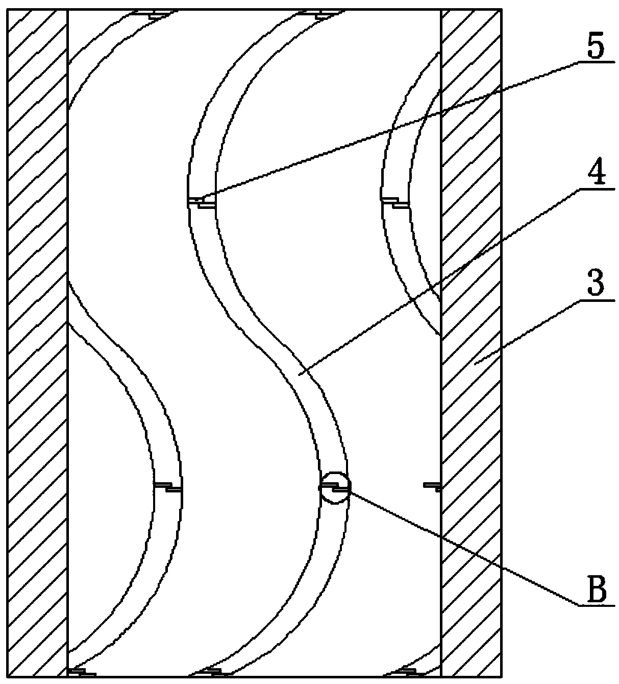
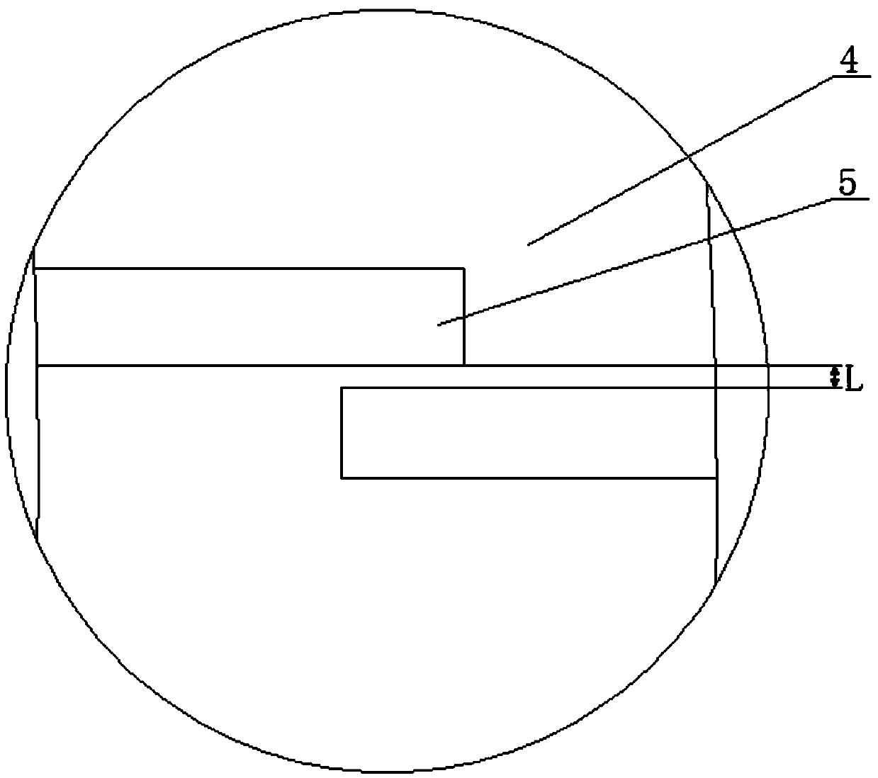

Image

  • Computerized embroidery machine thread combing structure
  • Computerized embroidery machine thread combing structure
  • Computerized embroidery machine thread combing structure

Examples


Embodiment Construction

[0011] The technical solutions of the present invention will be further specifically described below through the embodiments and in conjunction with the accompanying drawings.

[0012] Such as Figure 1 ~ Figure 3 As shown, a combing structure of a computer embroidery machine includes a base body 1, the upper part of the base body 1 is connected to a cylindrical roller body 3 through a flexible rod 2, the two ends of the cylindrical roller body 3 are open and the interior is hollow, and the inner wall of the cylindrical roller body 3 Grooves 4 are provided in the upper direction, the grooves 4 are S-shaped, the cross-section of the grooves 4 is an inverted triangle, and several pairs of guide bars 5 are arranged on each groove 4, and the two guide bars 5 of each pair are respectively located in the grooves. 4 and arranged alternately on both sides, the gap L between each pair of two guide strips 5 is 0.3-0.5mm, and the lower part of the base 1 is provided with a magnetic piece...


PUM


Abstract

The invention discloses a computerized embroidery machine thread combing structure. The computerized embroidery machine thread combing structure comprises a base body, wherein the upper portion of thebase body is connected with a cylindrical roller body through a flexible rod, the two ends of the cylindrical roller body are provided with openings, the inner portion of the cylindrical roller bodyis hollow, the inner wall of the cylindrical roller body is circumferentially provided with grooves, the grooves are in S shapes, the cross section of each groove is in an inverted triangle shape, each groove is provided with a plurality of pairs of guide strips, the two guide strips in each pair are located at the two sides of the corresponding groove and arranged staggeredly, a gap L between thetwo guide strips in each pair is 0.3-0.5 millimeter, and the lower portion of the base body is provided with a magnetic part. The computerized embroidery machine thread combing structure can comb threads before weaving embroidery to reduce thread residues or joint winding and ensure the embroidery quality.

Description

technical field [0001] The invention relates to a thread combing structure of a computerized embroidery machine. Background technique [0002] The embroidery machines currently on the market that use computer control to embroider and weave are prone to thread jams during the embroidery weaving process. This is because there will be some thread joints in the lines, and the thread ends or joints are not combed in time, which will lead to joints or thread ends during weaving and embroidery. Stuck in the woven parts, affecting the overall embroidery quality, and currently there is a lack of related structures, which need to be improved. Contents of the invention [0003] The purpose of the present invention is to overcome the disadvantages of the above-mentioned prior art, and provide a computerized embroidery machine combing structure that can comb the threads before weaving and embroidering, reduce the winding of threads or joints, and ensure the quality of embroidery. [0...

Claims


Application Information

Patent Timeline
IPC IPC(8): D05C11/00
CPCD05C11/00
Inventor 王立明
Owner SHAOXING KEQIAO TONGYI SCI & TECH INFORMATION CONSULTING CO LTD
Learn More