Vibration isolation piles and vibration isolation row of piles adopting vibration isolation piles

A technology of vibration isolation and pile body, which is applied in the direction of roads, tracks, protection devices, etc., can solve the problems of poor vibration isolation effect, and achieve the effect of improving vibration isolation effect and reducing effect

Pending Publication Date: 2019-07-05
广州市泰宇科技发展有限公司
View PDF0 Cites 2 Cited by
  • Summary
  • Abstract
  • Description
  • Claims
  • Application Information

AI Technical Summary

Problems solved by technology

[0007] Aiming at the technical problem of poor vibration isolation effect existing in the prior art, the present invention provides a vibration isolation pile

Method used


Image

  • Vibration isolation piles and vibration isolation row of piles adopting vibration isolation piles
  • Vibration isolation piles and vibration isolation row of piles adopting vibration isolation piles
  • Vibration isolation piles and vibration isolation row of piles adopting vibration isolation piles

Examples


Embodiment Construction

[0039] In order to better explain the present invention and facilitate understanding, the present invention will be described in detail below through specific embodiments in conjunction with the accompanying drawings.

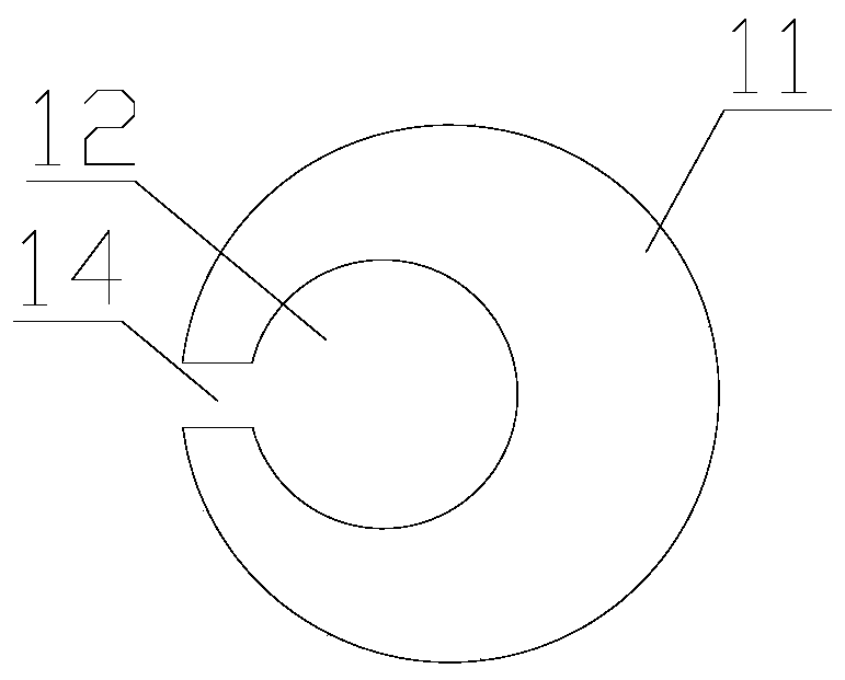
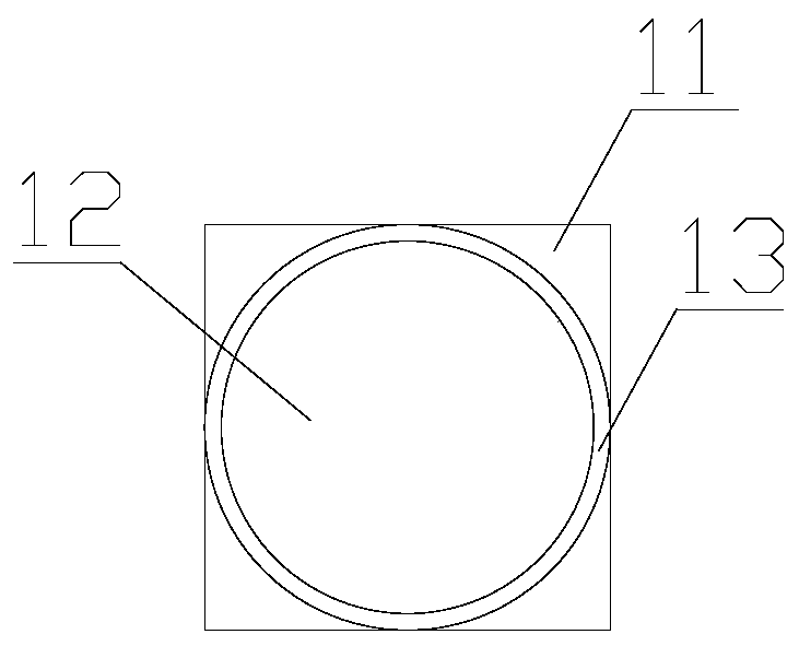
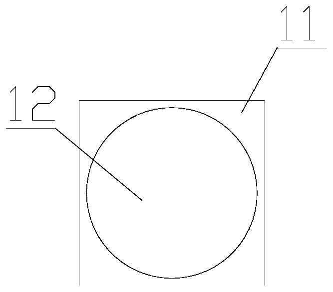
[0040] like Figure 1 to Figure 4 As shown, a vibration isolation pile 1 in this embodiment includes a pile body 11, and a cavity structure is arranged in the pile body 11, and the cavity in the pile body 11 forms a vibration isolation cavity 12 of the vibration isolation pile.

[0041] In this embodiment, the cavity structure may be arranged along the axial direction of the pile body 11 , or along the radial direction of the pile body 11 , or arranged obliquely relative to the axis of the pile body 11 .

[0042] The vibration isolation cavity 12 can be set through the pile body, or can not be set through the pile body 11 , or only one end of the vibration isolation cavity 12 can be set through the pile body 11 .

[0043] At least one vibration-isolation cavit...


PUM


Abstract

The invention belongs to the technical field of sound insulation and noise reduction equipment, and particularly relates to vibration isolation piles and a vibration isolation row of piles adopting the vibration isolation piles. Each vibration isolation pile includes a pile body, a cavity structure is arranged in each pile body, and a cavity in each pile body forms a vibration isolation cavity ofthe corresponding vibration isolation pile. The vibration isolation piles are arranged around a vibration source during use, when vibration waves pass through the vibration isolation piles, vibrationcan be subtracted in the vibration isolation cavities, and according to different types of the vibration waves, the positions and numbers of the vibration isolation cavities can be adjusted accordingly; and thus, the subduction effect of the vibration waves can further be improved, and the vibration isolation effect of the vibration isolation pipes is improved.

Description

technical field [0001] The invention belongs to the technical field of sound insulation and noise reduction equipment, and in particular relates to a vibration isolation pile and a vibration isolation pile arrangement using the same. Background technique [0002] In the current rail transit operation, vibrations caused by vehicles, tracks, and roadbed irregularities are transmitted through the foundation bed to the surrounding foundations along the line, which seriously affects the long-term use of surrounding buildings and the normal life of residents, and at the same time brings huge deviations in the measurement of precision instruments. Due to a series of adverse effects brought by vibration, it has been listed as one of the seven major environmental hazards internationally. [0003] In the control of rail transit roadbed vibration reduction and isolation measures, the main research is to control the vibration source and vibration wave propagation path, but in the proces...

Claims


Application Information

Patent Timeline
Patent Type & Authority Applications(China)
IPC IPC(8): E02D31/08E01B19/00
CPCE01B19/003E02D31/08E02D2300/002
Inventor 单泰雷
Owner 广州市泰宇科技发展有限公司
Why Eureka
Try Eureka