

Heat insulation protection structure of engine exhaust system
A technology of exhaust system and protective structure, applied in the direction of engine components, machines/engines, exhaust devices, etc., can solve the problems of gaps, unsightly appearance, bloated product design, etc., achieve strict protection and ensure water resistance Effect
- Summary
- Abstract
- Description
- Claims
- Application Information
AI Technical Summary
Problems solved by technology
Method used
Image

Examples
Embodiment 1
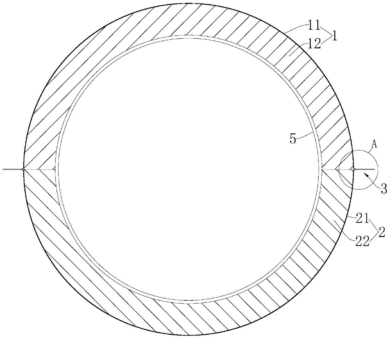
[0043] refer to Figure 1 to Figure 4 , an engine exhaust system heat insulation protection structure, comprising a first heat shield 1 and a second heat shield 2 .
[0044] Specifically, the shape of the first heat shield 1 and the shape of the second heat shield 2 are adapted to the shape of the outer surface 5 of the exhaust system, so as to facilitate covering on the outer surface 5 of the exhaust system. The first heat shield 1 and the second heat shield 2 are co-wrapped and fixed on the outer surface 5 of the exhaust system.
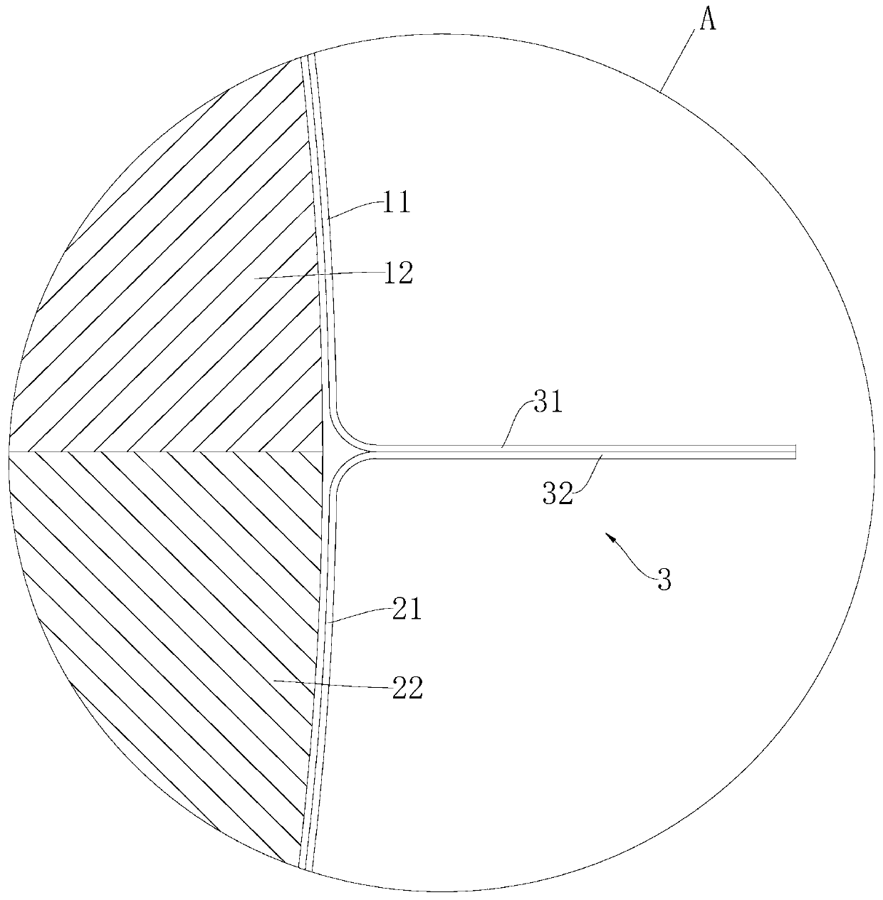
[0045] Among them, such as figure 2 with image 3 , the first heat shield 1 includes a first shield 11 and a first heat insulation layer 12 fixed inside the first shield 11 by gluing. The first protective cover 11 is fully welded and fixed to the outer surface 5 of the exhaust system to ensure tightness and play a waterproof role. The material of the first heat insulating layer 12 is other heat insulating materials such as ceramic fiber, glass...
Embodiment 2
[0053] Such as Figure 5 to Figure 7 As shown, the engine exhaust system heat insulation protection structure of this embodiment is basically the same as that of Embodiment 1, except that the structure of the lug structure 3 is different.
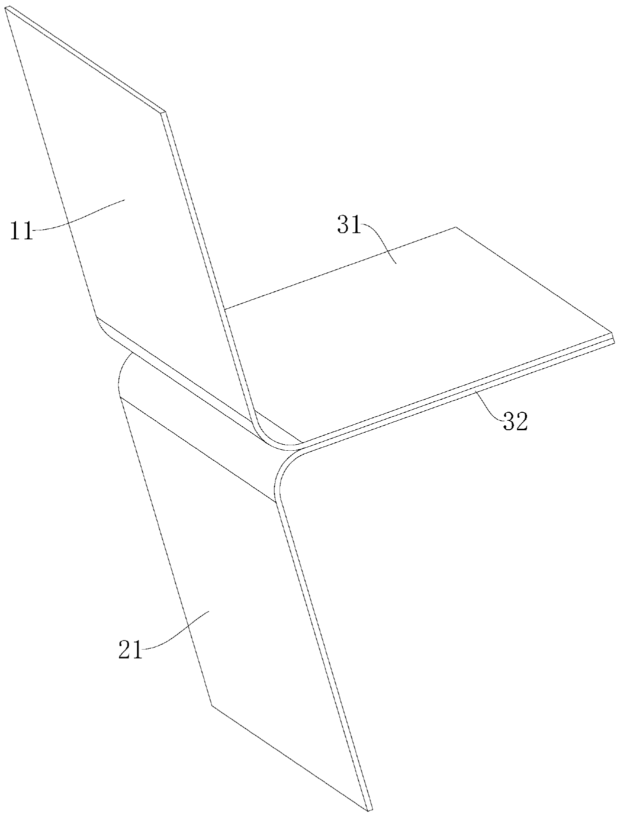
[0054] In this example, if Image 6 with Figure 7 , the lug structure 3 includes a first upright edge 31 arranged on the edge of the first protective cover 11 and a straight flange 33 arranged on the edge of the second protective cover 21, the first upright edge 31 Set opposite to the straight flange 33 .
[0055] The overall length of the straight flange 33 is greater than the overall length of the first vertical edge 31, the straight flange 33 closely fits the first vertical edge 31, and the outer end of the straight flange 33 is bent to form a second clamping The portion 331 wraps the first upright edge 31 , and the first upright edge 31 and the straight flange 33 are fully welded and fixed.
[0056] Such as Image 6 with Figure ...
Embodiment 3
[0059] Such as Figure 8 As shown, the engine exhaust system heat insulation protection structure of this embodiment is basically the same as that of Embodiment 1, except that the structure of the lug structure 3 is different.
[0060] In this embodiment, the lug structure 3 includes a folded edge 34 arranged on the edge of the first protective cover 11 and a double folded edge 35 arranged on the edge of the second protective cover 21, and the double folded edge 35 is arranged on the edge of the second protective cover 21. The folded edge 35 is opposite to the folded edge 34 .
[0061] The folded edge 34 is formed by bending a flange of the first protective cover 11 at a side close to the first protective cover 11 by 90°, and the folded edge 34 includes a flanged portion connected to the first protective cover 11 342 and the flanging portion 341 connected to the flanging portion 342.
[0062] The double folded edge 35 is formed by bending twice a flange of the second protect...
PUM
| Property | Measurement | Unit |
|---|---|---|
| Thickness | aaaaa | aaaaa |
| Thickness | aaaaa | aaaaa |
Abstract
Description
Claims
Application Information