Polishing device capable of achieving multi-axis switching

A polishing device and polishing wheel technology, which can be applied to grinding drive devices, surface polishing machine tools, grinding/polishing equipment, etc. The effect of polishing efficiency

Pending Publication Date: 2020-07-31
湖南安冠智能科技有限公司 +1
View PDF0 Cites 0 Cited by
  • Summary
  • Abstract
  • Description
  • Claims
  • Application Information

AI Technical Summary

Problems solved by technology

[0003] Traditional polishing equipment is mostly single or double polishing wheel equipment, and the polishing wheels cannot be switched or turned over, which has the following technical problems: (1) The speed of the polishing wheel is low (only 0-50rpm), the polishing time is long, and the production capacity is low; (2) The polishing wheel cannot be switched according to the process needs, the process path is single, the combination cannot be expanded, and the polishing efficiency is low; (3) The size of the polishing wheel is too large (the size of the p

Method used


Image

  • Polishing device capable of achieving multi-axis switching
  • Polishing device capable of achieving multi-axis switching
  • Polishing device capable of achieving multi-axis switching

Examples


Embodiment 1

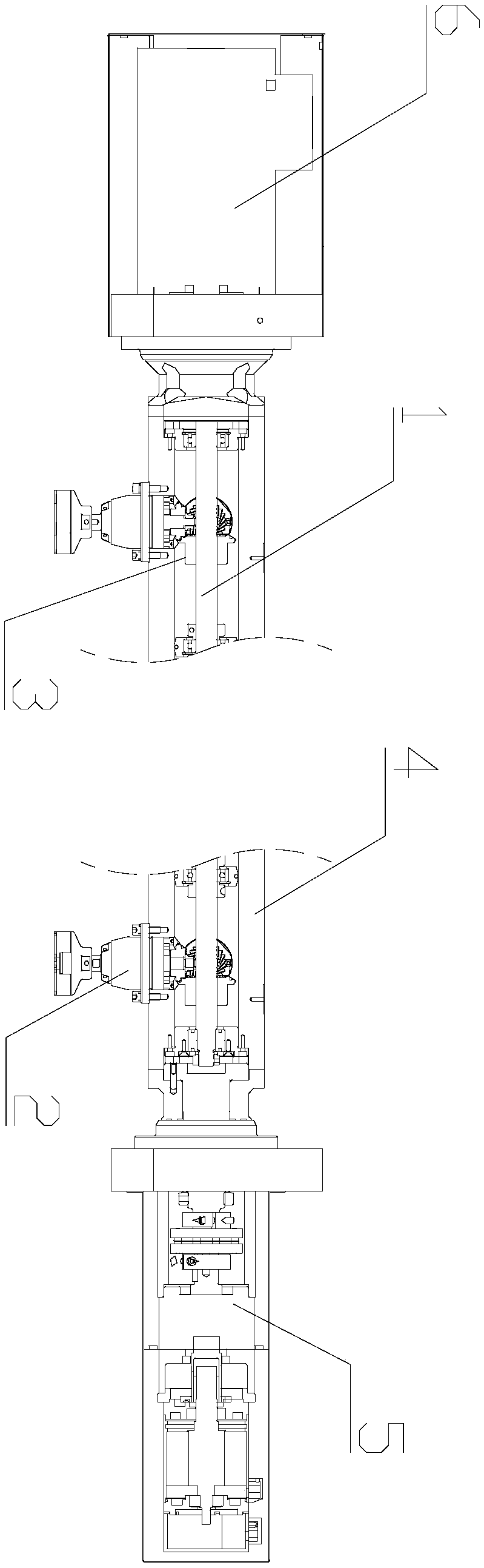
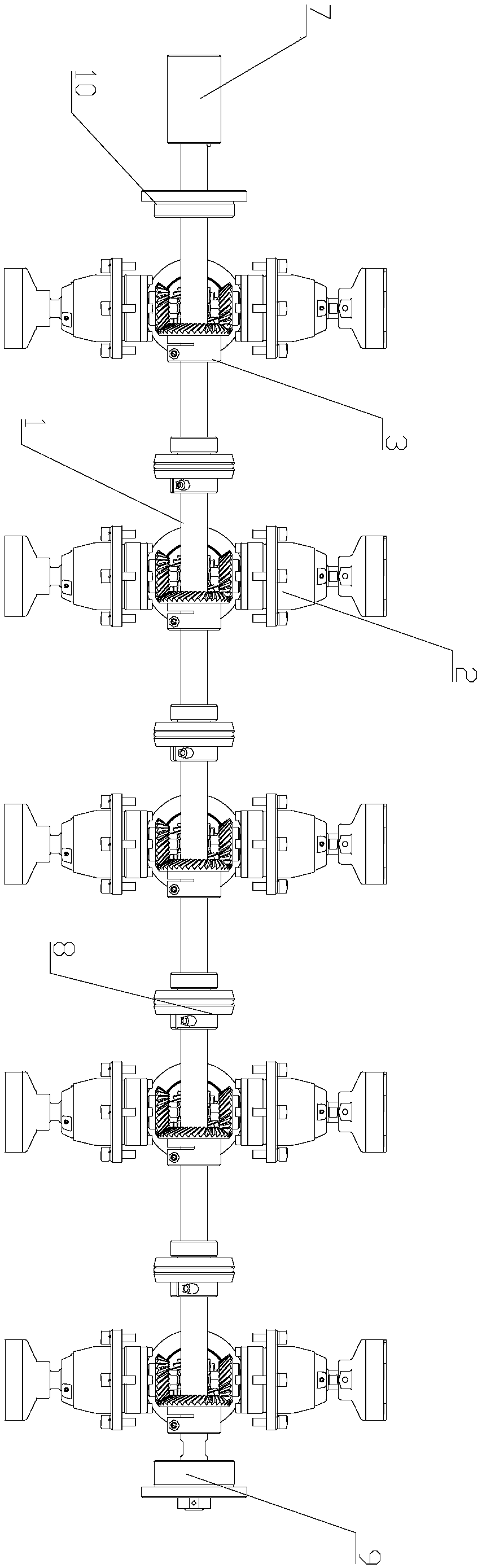
[0030] This embodiment provides a multi-axis switching polishing device, such as Figure 1-2 As shown, the device includes: a transmission shaft 1; a polishing wheel unit 2, the polishing wheel unit includes at least two polishing wheel assemblies 201, and the end of the polishing wheel assembly 201 is provided with a driven gear 2011; the driving gear 3 is sleeved on The transmission shaft 1 is outside, and is engaged with the driven gear 2011; the rotating beam 4, the polishing wheel unit 2 is connected to the rotating beam 4. In this embodiment, the driven gear 2011 is a spiral bevel gear, which has stable transmission, high bearing capacity, wear resistance, and low noise. Through this high-precision gear meshing action, it is further guaranteed that the polishing wheel assembly 201 can operate at a high speed. The beating is small when rotating, and the cutting force of polishing is more uniform, thus ensuring the consistency of polishing effect.

[0031] The models and ...

Embodiment 2

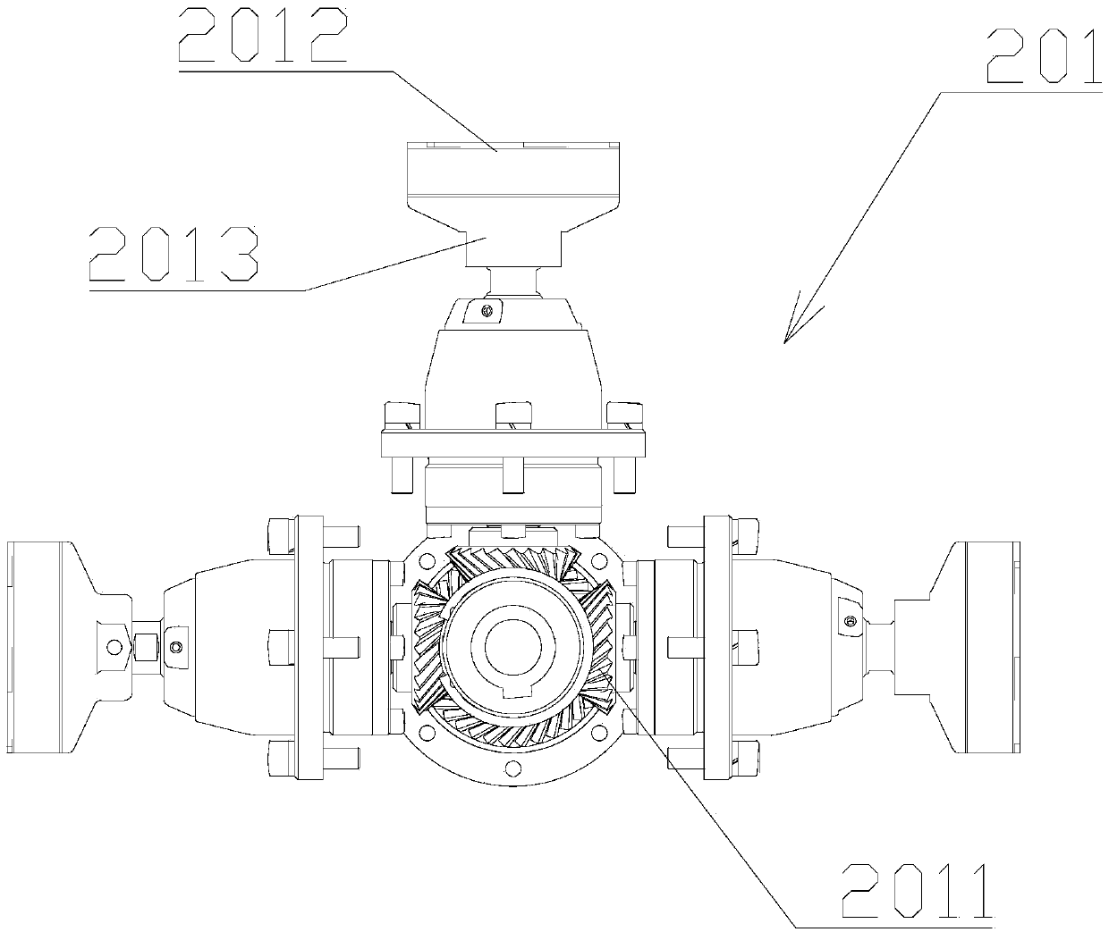
[0039] This embodiment provides a multi-axis switchable polishing device, the structure of which is basically the same as that of Embodiment 1. Specifically, in this embodiment, each polishing wheel unit 2 includes three polishing wheel assemblies 201, three polishing wheel assemblies The 201 is a different model. like image 3 As shown, the driven gears 2011 of the three polishing wheel assemblies 201 are meshed with the driving gear 3, and the revolution driving mechanism 5 drives the rotating beam 4 to rotate, thereby driving the polishing wheel unit 2 to rotate, so that different polishing The wheel assembly 201 rotates to a processing position to meet different processing requirements.


PUM

PropertyMeasurementUnit
Diameteraaaaaaaaaa
Diameteraaaaaaaaaa

Abstract

The invention belongs to the technical field of glass processing, and discloses a polishing device capable of achieving multi-axis switching. The polishing device comprises a transmission shaft, polishing wheel units, driving gears and a rotating cross beam, wherein each polishing wheel unit comprises at least two polishing wheel assemblies, and each polishing wheel assembly comprises a driven gear; the driving gears sleeve the transmission shaft and are connected with the driven gears in a matched mode; and the polishing wheel units are connected to the rotating cross beam. The rotating crossbeam rotates to drive the polishing wheel units to revolve, the types and the sizes of the polishing wheel assemblies in each polishing wheel unit can be different, the driving gears are connected with the driven gears in a matched mode, and under the driving of the driving gears, the different polishing wheel assemblies are switched for polishing processing, so that one main shaft drives the multiple sets of polishing wheel assemblies, different processing requirements can be met by combining the polishing wheel assemblies with different types, the expansibility is high, the polishing efficiency is high, and the device is compact in layout, tight in protection, convenient and fast to install and maintain, high in gear transmission precision, low in noise and long in service life.

Description

technical field [0001] The invention belongs to the technical field of glass processing, and relates to a polishing device, in particular to a multi-axis switching polishing device. Background technique [0002] Polishing is an important process in the glass processing process. It is a process of using mechanical surface grinding and chemical corrosion of polishing liquid to achieve a smooth and smooth glass surface. After polishing, the glass surface is smooth and bright, with a high aesthetic feeling, and the brightness of polishing directly affects the appearance quality of the product. [0003] Traditional polishing equipment is mostly single or double polishing wheel equipment, and the polishing wheels cannot be switched or turned over, which has the following technical problems: (1) The speed of the polishing wheel is low (only 0-50rpm), the polishing time is long, and the production capacity is low; (2) The polishing wheel cannot be switched according to the process ...

Claims


Application Information

Patent Timeline
IPC IPC(8): B24B27/00B24B29/00B24B41/04B24B47/12
CPCB24B27/0076B24B29/00B24B41/04B24B47/12
Inventor 彭富国刘光映
Owner 湖南安冠智能科技有限公司
Why Eureka
Try Eureka