
Actuator, energy filling device and vehicle

A technology for filling devices and actuators, which can be used in transmission devices, vehicle parts, transportation and packaging, etc., and can solve problems such as high cost and low reliability

Pending Publication Date: 2019-07-05
NIO ANHUI HLDG CO LTD
View PDF7 Cites 0 Cited by
  • Summary
  • Abstract
  • Description
  • Claims
  • Application Information

AI Technical Summary

Problems solved by technology

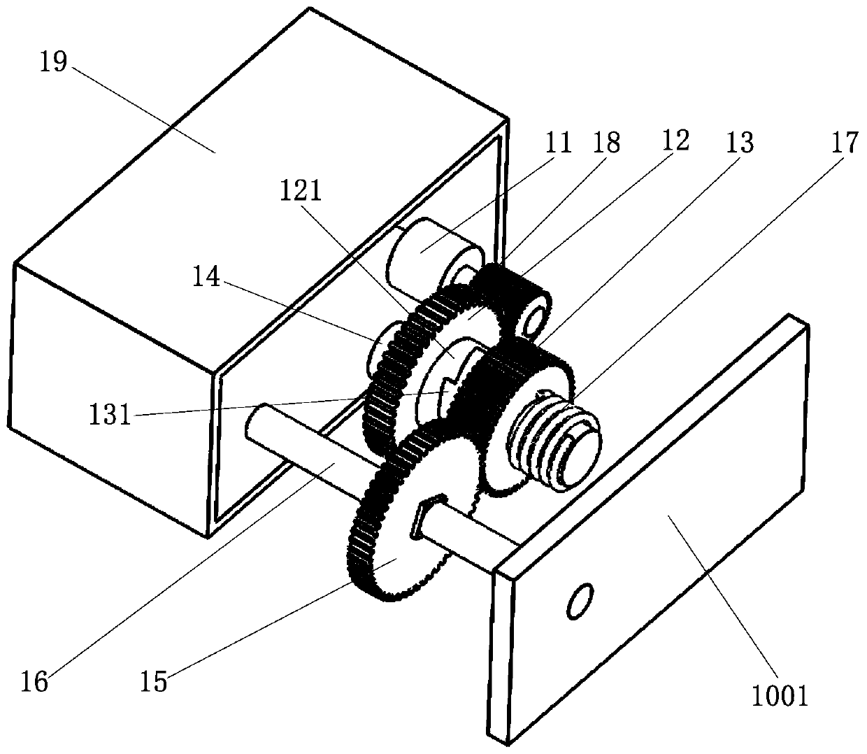
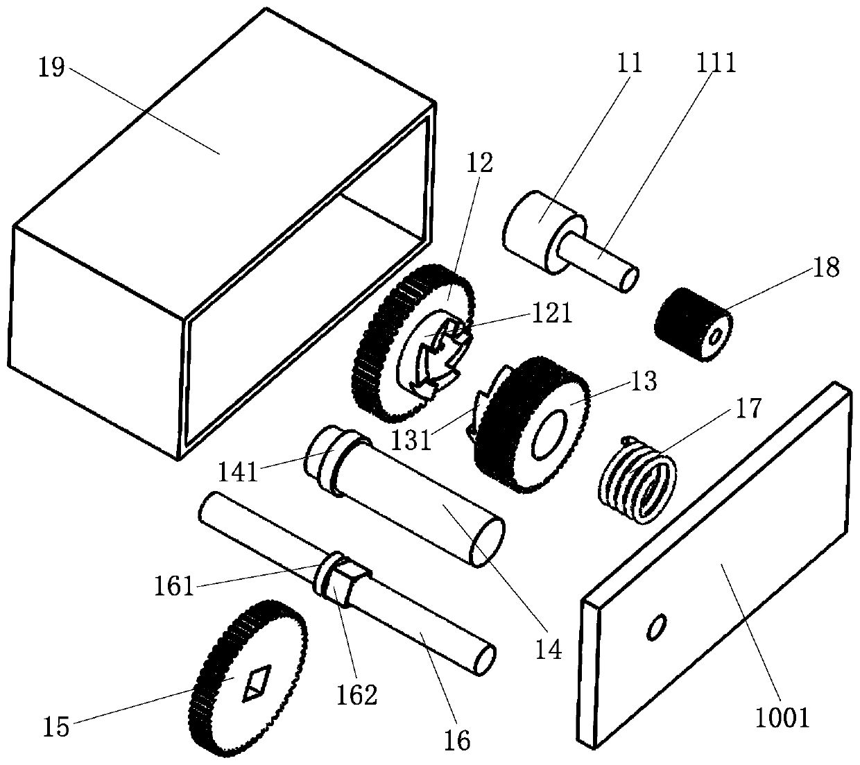
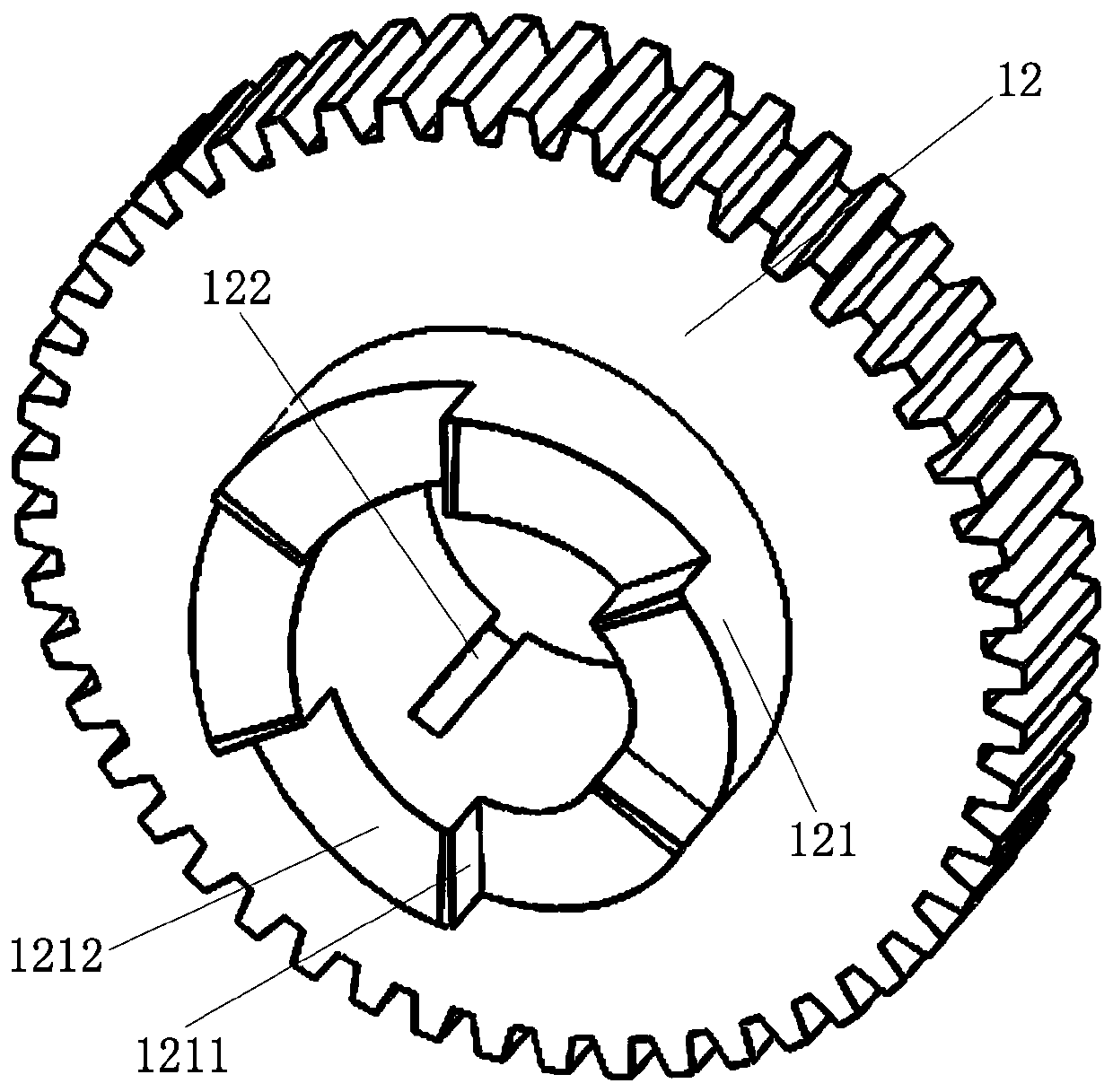
[0004] In order to solve the above-mentioned problems in the prior art, that is, in order to solve the problems of high cost and low reliability of existing one-way self-locking actuators, the present invention provides an actuator with one-way self-locking function, so The actuator includes a driving member, a first gear, a second gear, a third gear, a first connecting shaft, a second connecting shaft and an elastic member, and the first gear and the second gear are both arranged on the first On the connecting shaft, a first one-way sliding connection structure and a second one-way sliding connection structure are arranged between the first gear and the second gear, and the third gear is arranged on the second connecting shaft , and the third gear meshes with the second gear, the driving member is configured to drive the first gear to rotate in the power-on state and limit the rotation of the first gear in the power-off state, and When the driving member drives the first gear to rotate, the first one-way sliding connection structure and the second one-way sliding connection structure can be engaged with each other under the elastic action of the elastic member, so that the The second gear rotates, so that the third gear and the second connecting shaft rotate accordingly, and the elastic member allows the first unit to rotate under the condition that the driving member restricts the rotation of the first gear. Move back to the sliding connection structure and the second one-way sliding connection structure and make the second gear rotate only in the first direction, so that the third gear and the second connecting shaft can only rotate in the first direction Rotation in two directions, wherein one of the first direction and the second direction is clockwise and the other is counterclockwise

Method used


Image

  • Actuator, energy filling device and vehicle
  • Actuator, energy filling device and vehicle
  • Actuator, energy filling device and vehicle

Examples


Embodiment Construction

[0036] Preferred embodiments of the present invention are described below with reference to the accompanying drawings. Those skilled in the art should understand that these embodiments are only used to explain the technical principles of the present invention, and are not intended to limit the protection scope of the present invention. Those skilled in the art can make adjustments as needed so as to adapt to specific applications. For example, although the specification is described in conjunction with the situation when the actuator is used to drive a shielding component of a vehicle, the actuator of the present invention can obviously also be used to drive other components. Such changes in application objects do not deviate from the basic principle of the present invention, and therefore all will fall within the scope of protection of the present invention.

[0037] It should be noted that, in the description of the present invention, the terms "upper", "lower", "left", "ri...


PUM


Abstract

The invention belongs to the technical field of automatic control, and particularly provides an actuator, an energy filling device and a vehicle. The problem that an existing one-way self-locking actuator is high in cost and low in reliability is solved. The actuator comprises a driving component, a first gear, a second gear, a third gear, a first connecting shaft, a second connecting shaft and anelastic component. The first gear and the second gear are arranged on the first connecting shaft, and a first one-way sliding connecting structure and a second one-way sliding connecting structure are arranged between the first gear and the second gear. The third gear is arranged on the second connecting shaft, and the third gear is engaged with the second gear. Under the situation that the driving component limits rotation of the first gear, the elastic component allows the first one-way sliding connecting structure and the second one-way sliding connecting structure to move back to back, and the second gear can only rotate in the first direction. Therefore, the third gear and the second connecting shaft can only rotate in the second direction, and then a one-way self-locking function isachieved.

Description

technical field [0001] The invention belongs to the technical field of automatic control, and specifically provides an actuator, an energy filling device and a vehicle. Background technique [0002] With the continuous improvement of the degree of automation, the application of various automatic control components is becoming more and more extensive. Taking the actuator as an example, as the main component that can realize intelligent drive, the actuator plays a very important role in the field of automatic control. Generally, when dividing according to the state of the actuator after power failure, the existing actuators mainly include two categories: one is the self-locking actuator, that is, when the actuator is in the power-off state, the output shaft of the actuator It can neither rotate forward nor reverse; the other type is a non-self-locking actuator, that is, when the actuator is in a power-off state, the output shaft of the actuator can rotate both forward and rev...

Claims


Application Information

Patent Timeline
IPC IPC(8): F16H31/00B62D25/24
CPCF16H31/001B62D25/24
Inventor 李鹏
Owner NIO ANHUI HLDG CO LTD
Learn More