Tube explosion cut-off valve

A technology for cutting off valves and valve stems, applied in the field of valves, can solve problems such as failure to cut off pipes, destroy bridge sections, and cause social problems, etc., and achieve the effects of simple structure, reliable work and low production cost.

Pending Publication Date: 2019-07-05
ZHEJIANG BANNINGER FLUID CONTROL CO LTD
View PDF0 Cites 4 Cited by
  • Summary
  • Abstract
  • Description
  • Claims
  • Application Information

AI Technical Summary

Problems solved by technology

Once the pipe bursts, it is not only a huge waste of the medium itself, but more importantly, it may cause secondary disasters, damage public facilities, and wash away bridge sections, especially in hospitals, schools, gas stations and other areas. may cause social problems
[0003] Existing squib cut-off valves are generally butterfly type, and the valve operation is composed of a speed measuring device and external control components. The valve plate as the core component needs to be controlled by an external system to perform valve closing action, and the reliability is low, especially In places where the valve is installed in trenches, valve wells, etc., where it is inconvenient to maintain, once flooding or debris intrusion occurs, the transmission mechanism that is too long and too many outside the valve cannot maintain reliable operation for a long time to deal with random occurrences. pipe burst
At the same time, the existing squib cut-off valve is mainly to deal with the situation of downstream squib, and cannot realize the cutting function for upstream squib

Method used


Image

  • Tube explosion cut-off valve
  • Tube explosion cut-off valve
  • Tube explosion cut-off valve

Examples


Embodiment Construction

[0025] In order to make the purpose, technical solutions and advantages of the embodiments of the present invention clearer, the technical solutions in the embodiments of the present invention will be clearly and completely described below in conjunction with the drawings in the embodiments of the present invention. Obviously, the described embodiments It is a part of embodiments of the present invention, but not all embodiments. The components of the embodiments of the invention generally described and illustrated in the figures herein may be arranged and designed in a variety of different configurations. Accordingly, the following detailed description of the embodiments of the invention provided in the accompanying drawings is not intended to limit the scope of the claimed invention, but merely represents selected embodiments of the invention.

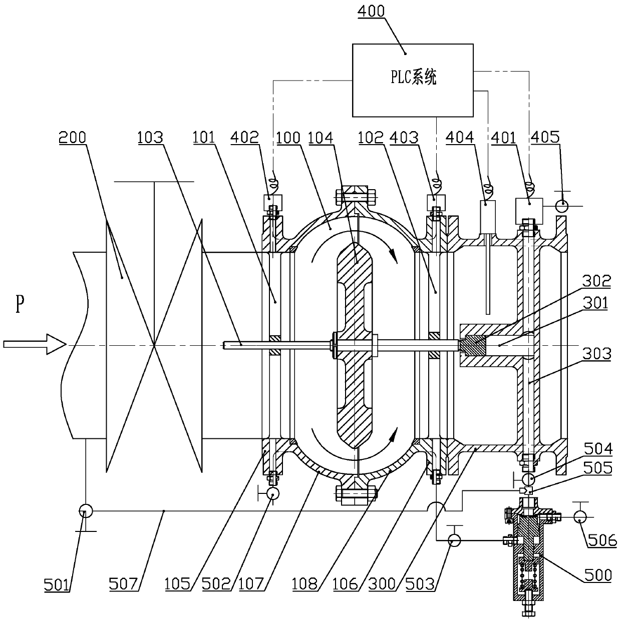
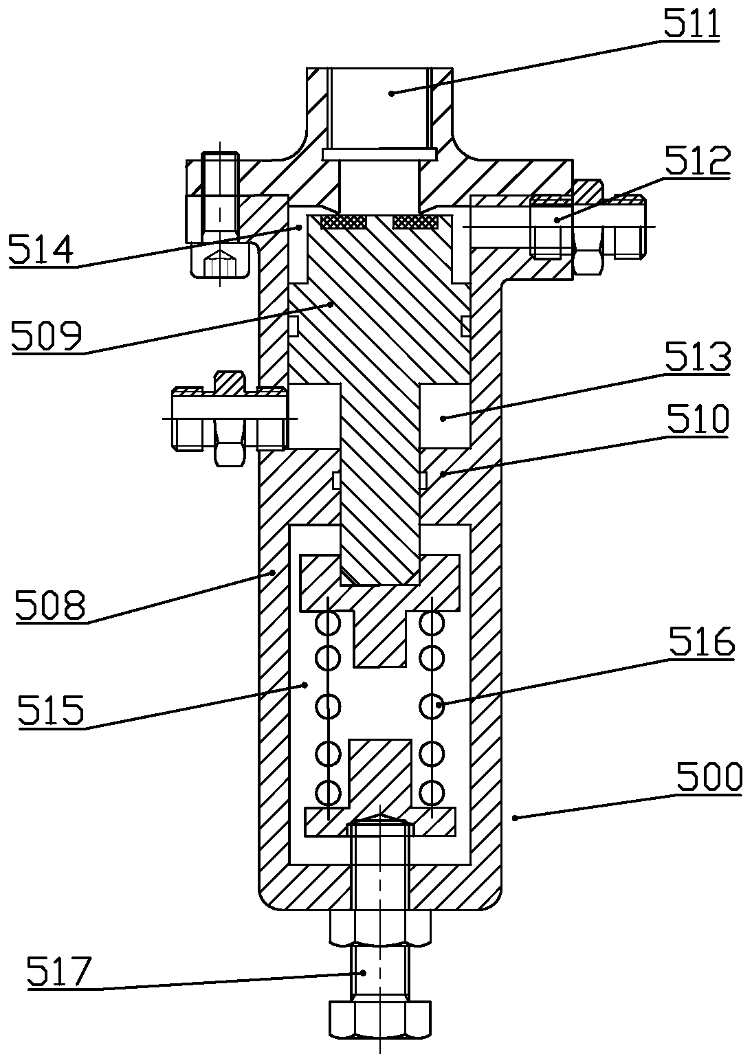
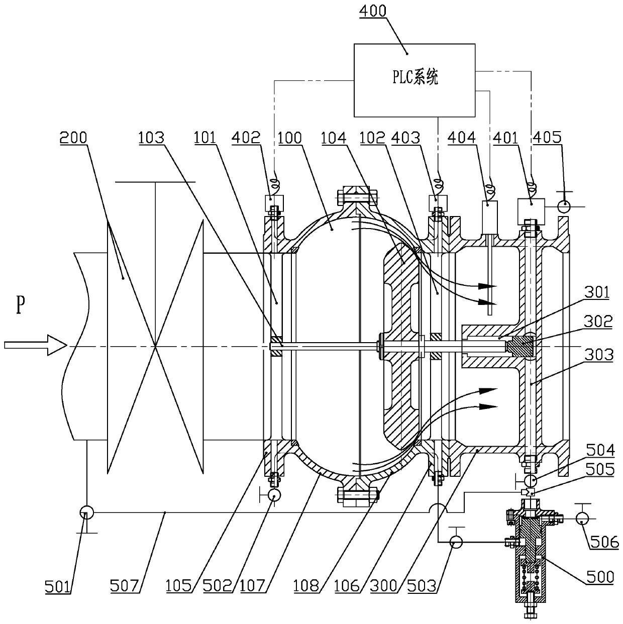
[0026] refer to figure 1 , image 3 and Figure 4 , the invention provides a squib shut-off valve, comprising:

[0027] The mai...


PUM


Abstract

The invention discloses a tube explosion cut-off valve which comprises a main valve body, a back valve body and an electromagnetic pilot valve system and / or a mechanical pilot valve system, wherein the main valve body is provided with a valve cavity, a first water inlet and a first water outlet; a valve rod is arranged in the main valve in a penetrating manner, the valve rod penetrates a valve cavity and is fixedly provided with a valve plate in the valve cavity, and the valve plate can close the first water inlet or the first water outlet; the back valve body is mounted on the main valve bodyand communicates to the first water outlet, the back valve body is provided with a first piston cavity, a sensing piston is mounted in the first piston cavity, a penetrating hole is formed in the end, close to the valve rod, of the first piston cavity, a sensing channel is also formed on the back valve body, and the sensing channel communicates to the first piston cavity; and the electromagneticpilot valve system and / or the mechanical pilot valve system communicates to the sensing channel and is started automatically when a pressure value in the sensing channel reaches a set value or is greater than the set value. The tube explosion cut-off valve not only can cut-off a water flow upstream during tube explosion, but also can cut-off the water flow downstream during tube explosion, and ishigh in cut-off efficiency, reliable to work, relatively low in production cost and high in environmental adaptability.

Description

technical field [0001] The invention belongs to the technical field of valves, in particular to a squib cut-off valve. Background technique [0002] Most of the water pipeline network is buried underground, and it is basically impossible to carry out daily maintenance and maintenance. Due to the action of soil corrosion and electrochemical corrosion, the water supply pipeline buried underground for a long time will cause the pipe wall to become thinner and the strength to decrease, thereby increasing the occurrence of explosions. Manage the chance of accidents. In addition, the reduction of the cross-section of the water flow, the reduction of the water flow capacity, the increase of the resistance of the pipeline, and the overload operation of the pipeline caused by the scaling of the pipeline are also likely to cause a pipe burst. For pipelines that are too old, under the interaction of corrosion and scaling, pipe wall fatigue, coupled with changes in ground loads and sea...

Claims


Application Information

Patent Timeline
Patent Type & Authority Applications(China)
IPC IPC(8): F16K17/36F16K37/00
CPCF16K17/36F16K37/005
Inventor 何锐刘卫理朱铁强
Owner ZHEJIANG BANNINGER FLUID CONTROL CO LTD
Why Eureka
Try Eureka