

Naturally driven indoor air machine
An indoor air-driven technology, applied in the direction of engine components, machines/engines, mechanical equipment, etc., can solve the problems of high power consumption and poor air exchange efficiency.
- Summary
- Abstract
- Description
- Claims
- Application Information
AI Technical Summary
Problems solved by technology
Method used
Image

Examples
Embodiment 1
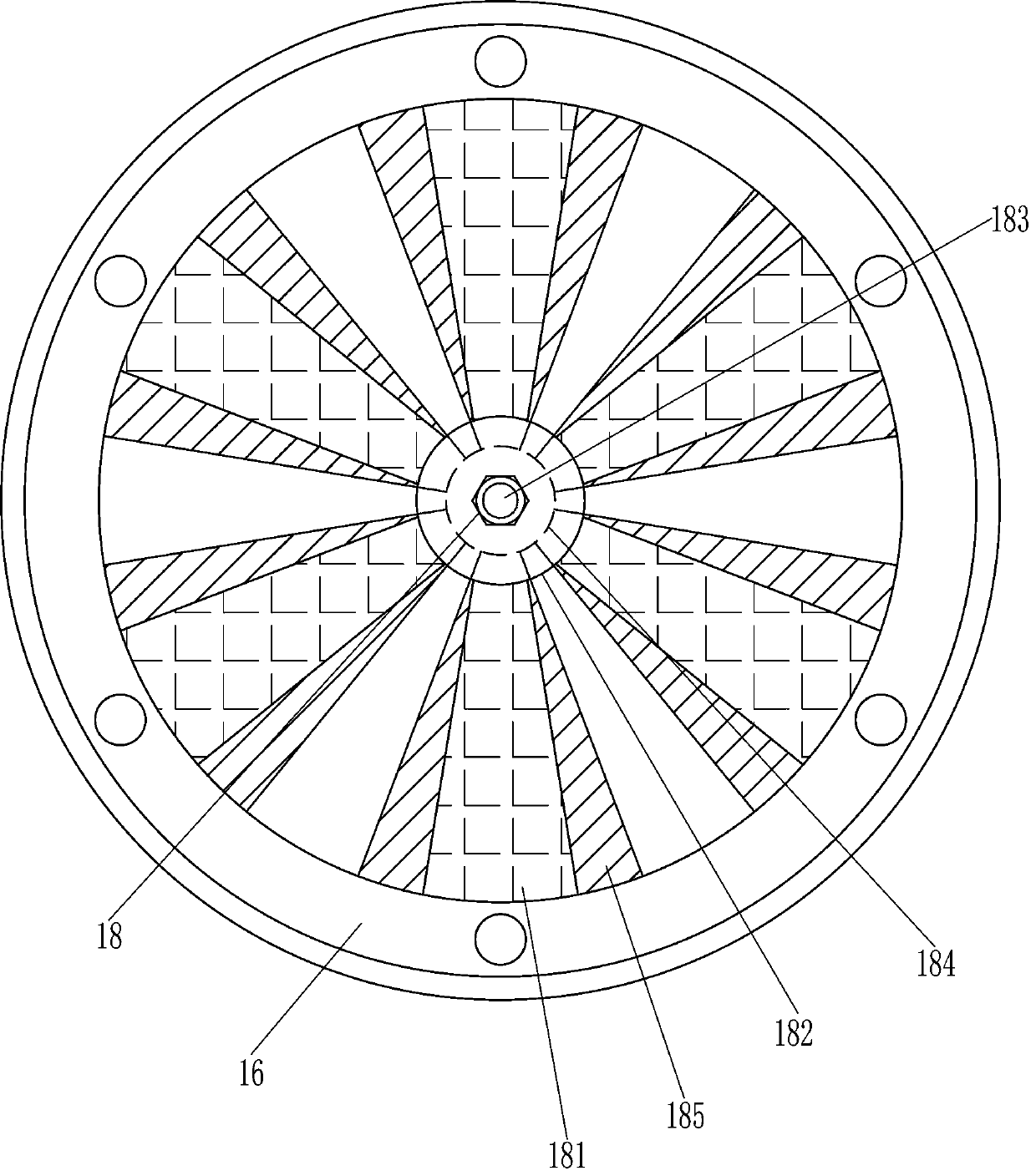
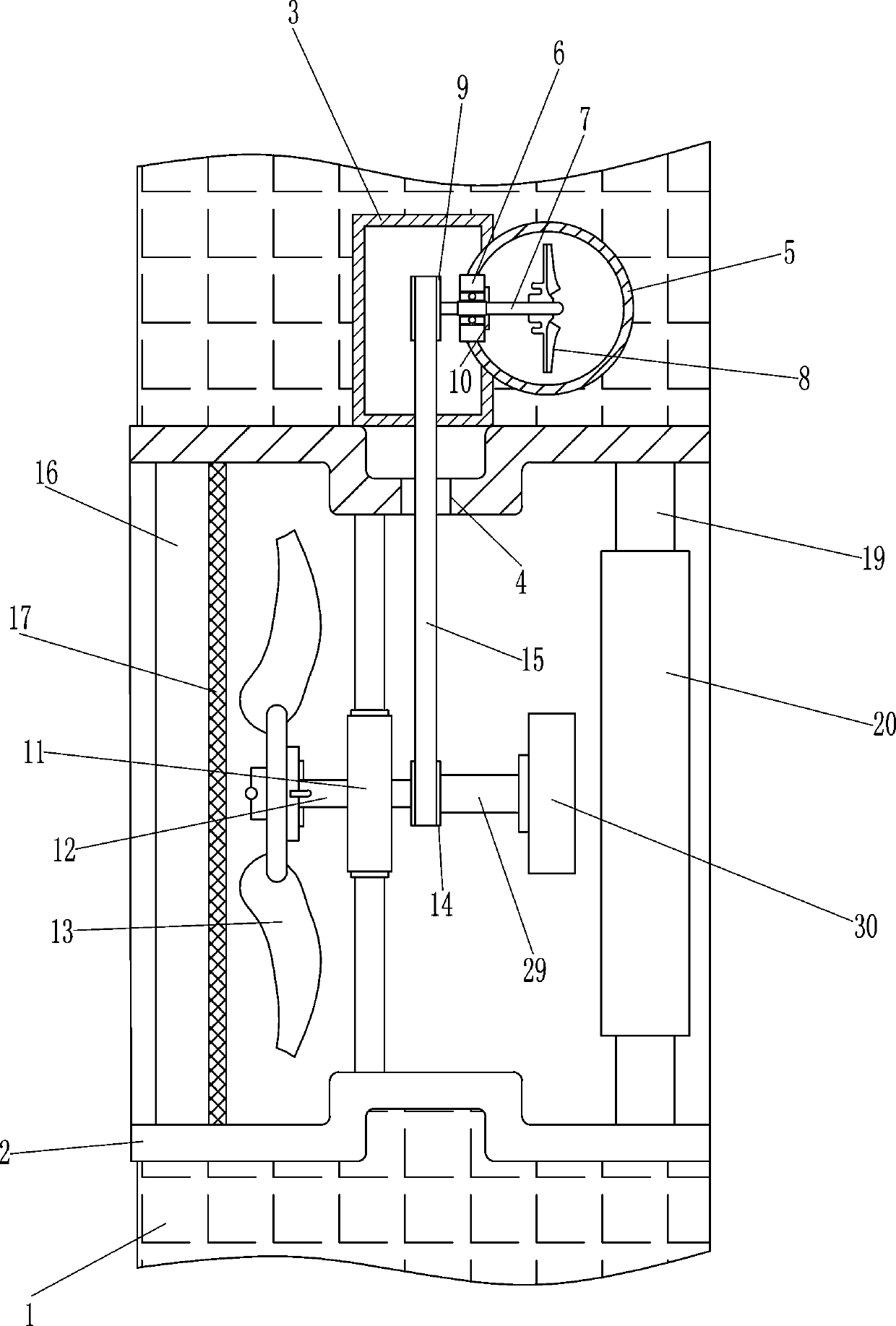
[0019] A nature-driven indoor air machine such as Figure 1-3 As shown, it includes a mounting sleeve 2, a housing 3, a connecting sleeve 5, a first bearing seat 6, a first rotating shaft 7, a water wheel 8, a first pulley 9, a sealing ring 10, a second bearing seat 11, and a second rotating shaft 12. Exhaust fan 13, second pulley 14, flat belt 15, first installation ring 16, isolation screen 17, ventilation size control device 18, support block 19, second installation ring 20, support rod 21, ring 22 , snap ring 25, activated carbon tube 26, second bolt 27 and first fastening nut 28, the first through hole 4 that plays a guiding role is opened in the middle of the top of the installation sleeve 2, and the first through hole 4 is fixed between the left part of the installation sleeve 2. An installation ring 16, the installation sleeve 2 is connected to the first installation ring 16 by welding, the first installation ring 16 is provided with a ventilation size control device 1...
Embodiment 2
[0021] A nature-driven indoor air machine such as Figure 1-3As shown, it includes a mounting sleeve 2, a housing 3, a connecting sleeve 5, a first bearing seat 6, a first rotating shaft 7, a water wheel 8, a first pulley 9, a sealing ring 10, a second bearing seat 11, and a second rotating shaft 12. Exhaust fan 13, second pulley 14, flat belt 15, first installation ring 16, isolation screen 17, ventilation size control device 18, support block 19, second installation ring 20, support rod 21, ring 22 , snap ring 25, activated carbon tube 26, second bolt 27 and first fastening nut 28, the first through hole 4 that plays a guiding role is opened in the middle of the top of the installation sleeve 2, and the first through hole 4 is fixed between the left part of the installation sleeve 2. An installation ring 16, the first installation ring 16 is provided with a ventilation size control device 18, an isolation screen 17 is fixedly connected between the right part of the inner sid...
Embodiment 3
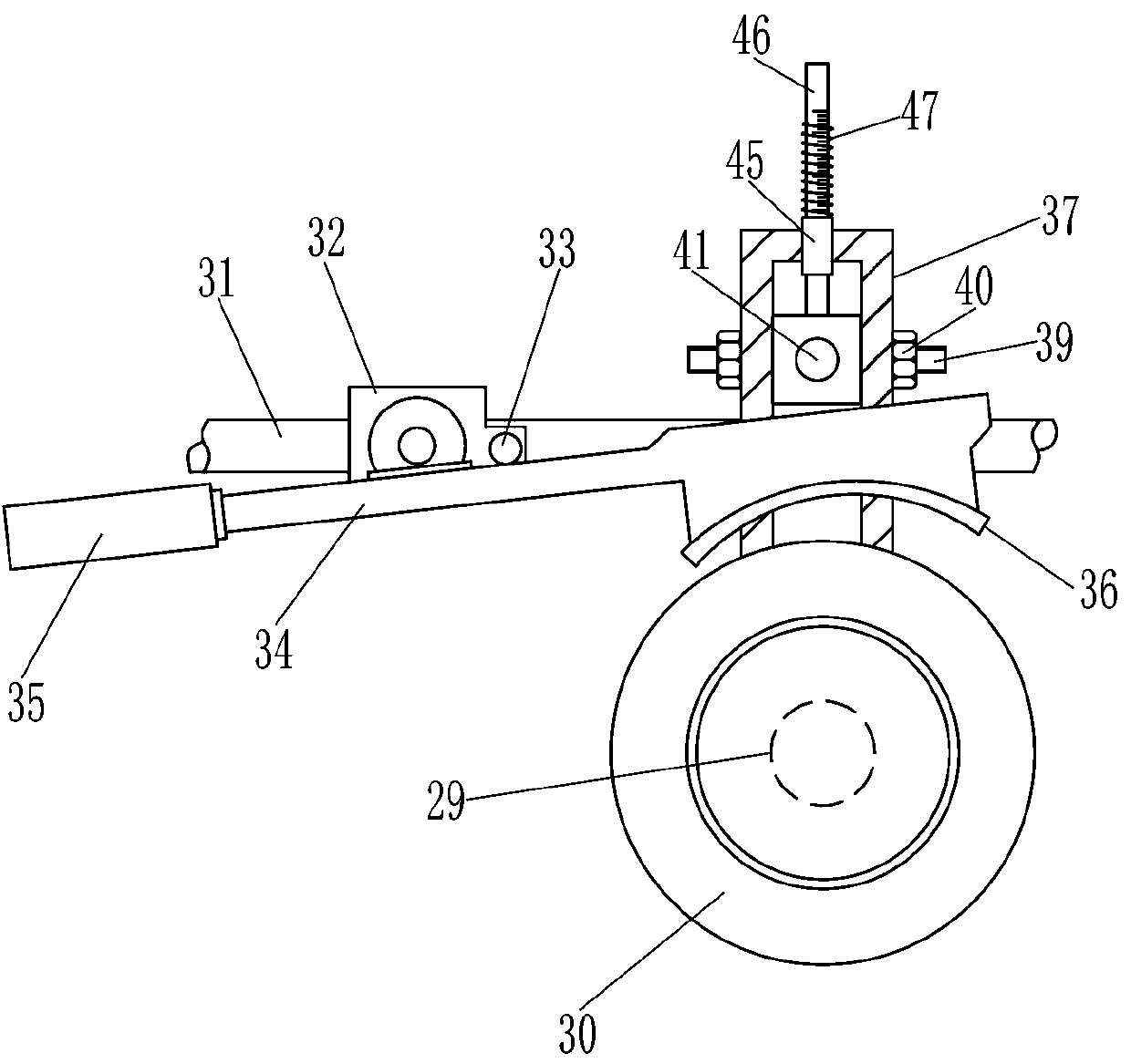
[0024] A nature-driven indoor air machine such as Figure 1-5 As shown, it includes a mounting sleeve 2, a housing 3, a connecting sleeve 5, a first bearing seat 6, a first rotating shaft 7, a water wheel 8, a first pulley 9, a sealing ring 10, a second bearing seat 11, and a second rotating shaft 12. Exhaust fan 13, second pulley 14, flat belt 15, first installation ring 16, isolation screen 17, ventilation size control device 18, support block 19, second installation ring 20, support rod 21, ring 22 , snap ring 25, activated carbon tube 26, second bolt 27 and first fastening nut 28, the first through hole 4 that plays a guiding role is opened in the middle of the top of the installation sleeve 2, and the first through hole 4 is fixed between the left part of the installation sleeve 2. An installation ring 16, the first installation ring 16 is provided with a ventilation size control device 18, an isolation screen 17 is fixedly connected between the right part of the inner si...
PUM
 Abstract
Description
Claims
Application Information