Multi-channel stepped electric gas control valve

A gas adjustment, step-type technology, applied in the direction of multi-way valves, fuel supply adjustment, valve details, etc., can solve the problem of gas channels that cannot be used for ignition or large fires, where the relative position cannot be accurately determined, and the ignition cannot be adjusted independently, etc. problem, to achieve the effect of accurate system closed-loop adjustment

Inactive Publication Date: 2010-04-21
FOSHAN CHANCHENG HENGDELI ELECTRIC APPLIANCE FACTORY
View PDF1 Cites 18 Cited by
  • Summary
  • Abstract
  • Description
  • Claims
  • Application Information

AI Technical Summary

Problems solved by technology

[0004] The Chinese Patent Gazette discloses a "double-closed adjustable flow gas valve", whose publication number is CN1601184. This double-closed adjustable flow gas valve can only close the gas passage of the fire and the fire at the same time, but cannot separately close the fire. Or the gas channel of the large fire; the gas flow of the fire is only a fixed value and cannot be adjusted separately; and the adjustment of the large fire cannot accurately determine the relative position of the regulating body and the regulating port, so the adjustment can only be performed in open-loop control. When the flow valve is under open-loop control, it is difficult to accurately control the flow rate, and this situation will become more obvious after several repeated adjustments
Therefore, in the prior art, there has not been seen that only one electric or electromagnetic gas regulating valve can simultaneously independently and accurately regulate the gas flow of multiple gas channels or shut off the respective gas channels.

Method used


Image

  • Multi-channel stepped electric gas control valve
  • Multi-channel stepped electric gas control valve
  • Multi-channel stepped electric gas control valve

Examples


Embodiment 1

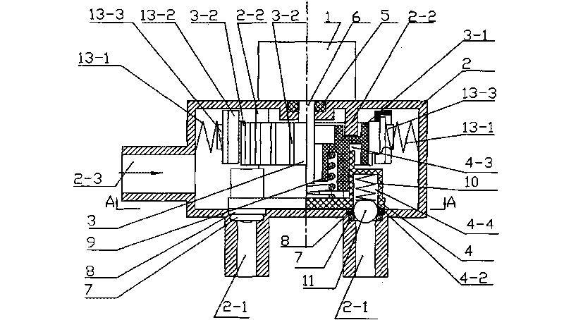
[0030] see figure 1 , figure 2 As shown, a mechanical multi-channel step-type electric gas regulating valve is composed of a geared motor 1, a valve housing 2, a positioner 3, an air distributor 4, and a positioner rotation angle detection mechanism. A geared motor 1 is installed on the outer side of the valve housing 2, a housing wall. The drive shaft 6 of the geared motor 1 extends into the valve body 2 and is sealed with the housing wall through an O-ring 5. The valve housing 2 perpendicular to the drive shaft 6 The other housing wall is provided with two air outlets 2-1, and the valve housing 2 is also provided with an air inlet 2-3. A cylindrical locator 3 is installed on the drive shaft 6 , and a group of vertical and parallel protruding teeth 3 - 2 are arranged on the outer circumference of the locator 3 as the positioning nodes of the locator 3 . The circular air distributor 4 is slidingly connected with the positioner 3 through its own spline 4-3 and the spline 3-1...

Embodiment 2

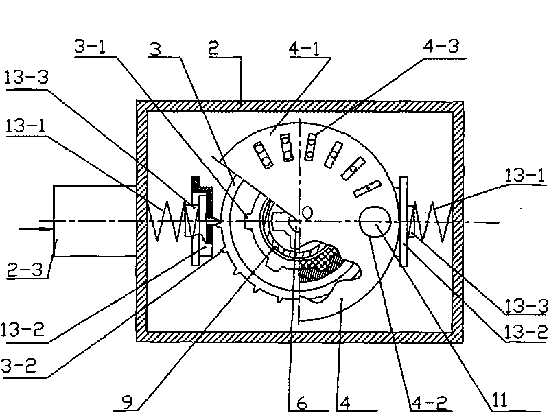
[0032] see image 3 As shown, this example is a magnetoelectric multi-channel step-type electric gas control valve, that is, the positioner rotation angle detection mechanism adopts a magnetoelectric structure, and other structures are the same as in Embodiment 1. The rotation angle detection mechanism of the magnetoelectric positioner consists of a row of permanent magnet blocks 15 installed at the same horizontal position on the outer circumference of the positioner 3 and a Hall element fixed on the inner wall of the valve housing 2 opposite to the row of permanent magnet blocks 15 16 compositions. When the locator 3 rotates, the Hall element will send the position signal of the locator 3 to the control circuit to control the output of the gas under the action of the permanent magnet blocks 15 .

Embodiment 3

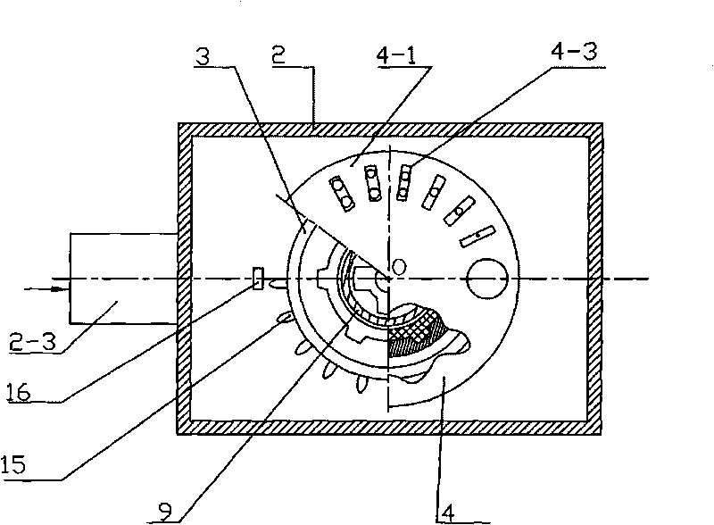
[0034] see Figure 4 As shown, this example is a photoelectric multi-channel step-type electric gas regulating valve, that is, the positioner rotation angle detection mechanism adopts a photoelectric structure, and other structures are the same as in Embodiment 1. The photoelectric positioner rotation angle detection mechanism consists of a row of through holes 17 located at the same horizontal position on the outer circumference of the positioner 3, and light-emitting diodes 18 and photoelectric receivers that are respectively located on both sides of the row of through holes 17 and fixed on the valve housing 2. Tube 19 is composed. When the positioner 3 rotates, the light emitted by the light-emitting diode 18 passes through the through hole 17 and is received by the photoelectric receiving tube 19 and outputs the position signal of the positioner 3 to the control circuit at this time, so as to realize the control of the gas output.


PUM


Abstract

The invention discloses a multi-channel stepped electric gas control valve which mainly comprises a valve shell, a speed reducing motor, a locator, an airflow distributor and a circular disk thereof and a locator rotational angle detection mechanism, wherein one side surface of the valve shell provided with a plurality of gas outlets is vertical to the driving shaft of the motor; the center lines of the driving shaft, the locator and the airflow distributor and the circular disk thereof are superposed; the circular disk is provided with starting holes and a plurality of groups of airflow distribution hole slots the number of which is the same as that of the gas outlets, wherein each hole slot is provided with through holes with different cross-section areas; the circular disk is closely clung to a rigid hollow washer arranged at the inner end opening of each gas outlet; locating joints which correspond to each group of hole slots with the same serial number are arranged on the outer periphery of the locator, and a locating end is arranged in the corresponding valve shell. The gas control valve is controlled exactly by action position feedback signals and a control circuit, multi-level stepped gas flow control can be carried out on a plurality of paths of gas channels, and the plurality of paths of gas channels can be shut off separately.

Description

technical field [0001] The invention relates to the technical field of gas flow regulating valves, in particular to a multi-channel step-type electric gas regulating valve. Background technique [0002] In the prior art, the gas control valve mainly uses the electromagnetic linear gradient gas flow adjustment method. This solenoid valve uses an electromagnet as a driving element, and the purpose of changing the gas flow is achieved by changing the current of the electromagnet coil winding. The current value of the solenoid coil is close to a linear relationship with the change of the gas flow. This kind of solenoid valve is often used for constant temperature regulation of gas water heaters. It is characterized by fast adjustment speed and large working current. However, when a certain gas flow needs to be maintained, a certain amount of electric energy is still consumed; a solenoid valve can only adjust the gas flow of one gas channel; and the product requires high processi...

Claims


Application Information

Patent Timeline
Patent Type & Authority Applications(China)
IPC IPC(8): F16K11/072F16K27/04F16K31/04
CPCF16K27/045Y10S137/905F16K27/048F16K11/072F16K31/042F16K31/041F23N1/007Y10T137/86863Y10T137/86493Y10T137/86533Y10T137/8242F23N2235/24
Inventor 潘兆铿
Owner FOSHAN CHANCHENG HENGDELI ELECTRIC APPLIANCE FACTORY
Why Eureka
Try Eureka