Permanent-magnet brushless self-adaptive variable-speed drive motor

A variable-speed drive, permanent magnet brushless technology, applied in the direction of magnetic circuit rotating parts, electrical components, electromechanical devices, etc., can solve the problems of high manufacturing and use cost, large number of parts, complex mechanism, etc. The process is simple and the effect of increasing the volume of the motor

Inactive Publication Date: 2014-02-12
杨荷
View PDF11 Cites 20 Cited by
  • Summary
  • Abstract
  • Description
  • Claims
  • Application Information

AI Technical Summary

Problems solved by technology

[0006] These foreign patents all use two or more permanent magnet rotors, and use electromagnets or motors to change the position of one of the rotors to change the air gap magnetic field. Although the purpose of adjusting the flux linkage can be achieved, the mechanism is relatively complicated. , the number of parts is large, and additional power consumption is required, and the manufacturing and use costs are relatively high

Method used


Image

  • Permanent-magnet brushless self-adaptive variable-speed drive motor
  • Permanent-magnet brushless self-adaptive variable-speed drive motor
  • Permanent-magnet brushless self-adaptive variable-speed drive motor

Examples


Embodiment 1

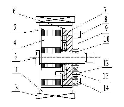
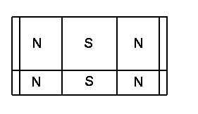
[0026] Example 1 see figure 1 and figure 2 , the main structure of the present invention is as follows: iron core 1 and winding 2 form the same stator part as the common brushless motor, the rotor shaft 3 is arranged in the center of the stator, the main rotor 4 is connected on the rotor shaft 3, and the permanent magnet 5 is arranged on its upper circumference, so that The polarity is periodically distributed according to N and S. The main rotor 4 needs to occupy most of the air gap of the stator, undertake the main function of energy conversion, and be fixedly connected with the rotor shaft 3, and output mechanical torque through the rotor shaft 3; on the rotor shaft 3 1. One end of the main rotor is the magnetic modulation rotor 7, and the magnetic modulation rotor 7 is provided with permanent magnets 6 in the circumferential direction, and the polarities are periodically distributed according to N and S. It can rotate a certain angle around the axis, change the magnetic ...

Embodiment 2

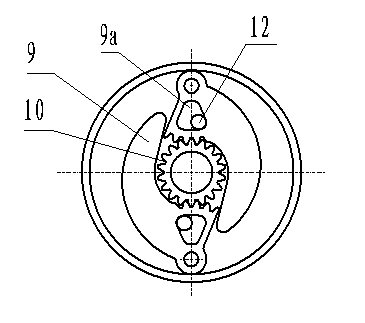
[0049] Embodiment 2 structure sees Figure 8 , In this example, the pin chute mechanism is used to replace the gear mechanism in Example 1, and the motion law is equivalent to the guide rod mechanism in mechanical design. The mechanism is described below, and the remaining motor parts are the same as in Embodiment 1. The centrifugal shoe 9 is connected to the magnetic adjustment rotor 7 through the shoe shaft 8. The centrifugal shoe 9 has a limit hole 11 and an elongated hole 14, and the pin 15 on the turntable 10 is embedded in the elongated hole to form a pin chute mechanism. The turntable 10 is fixed on the rotor shaft, the limit pin 12 is placed in the limit hole 11 and fixed on the end face of the speed-regulating rotor 7, so the magnetic-regulating rotor 7 can rotate along the turntable 10 in a certain range, and the other side of the speed-regulating rotor 7 A spring 13 is arranged on one side, and one end of its elastic force acts on the magnetizing rotor 7, and the o...

Embodiment 3

[0051] Embodiment 3 structure sees Figure 11 , which is characterized in that two magnetically adjustable rotors can also be used, which are symmetrically arranged at both ends of the main rotor, and jointly occupy the remaining part of the air gap. They have the same structure, but the rotational adjustment direction is symmetrical and opposite. This symmetrical design increases the cost. , but the adjustment process only changes the magnitude of the magnetic flux, does not change the phase of the magnetic flux, the magnetic flux waveform is better, and the control is simpler.


PUM


Abstract

The invention discloses a permanent-magnet brushless self-adaptive variable-speed motor. The permanent-magnet brushless self-adaptive variable-speed motor comprises a stator, a rotor shaft, a rotor and a centrifugal magnetism adjusting mechanism. The permanent-magnet brushless self-adaptive variable-speed motor is characterized in that the rotor of the motor is divided into more than two parts, one part is a main rotor part, occupies most area of a stator air gap, is mainly used for energy conversion and fixedly connected with the rotor shaft, and output mechanical torque through a rotary shaft, the remaining part is a magnetism adjusting rotor part, is arranged on one side of the main rotor part on the shaft and can rotate by a certain angle around the shaft, the shoe block type centrifugal magnetism adjusting mechanism is arranged on the magnetism adjusting rotor part, is coupled with a center wheel installed on the rotor shaft and can rotate around the center wheel, a reset spring is fixed between the magnetism adjusting rotor part and the main rotor part, angular displacement happens to the magnetism adjusting rotor part according to the change of the rotating speed under the combined action of centrifugal force and spring force and then the state of flux linkage is changed, the motor can be self-adaptive to the change of the moment of resistance, the characteristic of the constant torque at a rated speed and constant-power variable speed at a speed higher than the rated speed of the motor is achieved, and the characteristic is particularly suitable for driving vehicles.

Description

technical field [0001] The invention relates to a permanent magnet brushless motor, in particular to a permanent magnet brushless motor for driving an electric vehicle. Background technique [0002] In recent years, due to the development of motor and control technology and the requirements of environmental protection, electric vehicles have developed rapidly, and the drive motor, as a key part of it, plays a very important role. Among them, the permanent magnet brushless motor has been widely used in existing electric vehicles due to its compact structure, high specific power, high efficiency and mature technology. [0003] However, ordinary permanent magnet brushless motors are difficult to adjust the magnetic flux of the motor, and it is difficult to have the constant power speed regulation characteristics required for vehicle driving. The high-efficiency area of ​​its mechanical characteristics cannot cover the variation range of actual operating conditions, which is ver...

Claims


Application Information

Patent Timeline
Patent Type & Authority Applications(China)
IPC IPC(8): H02K16/02H02K1/27
Inventor 杨荷
Owner 杨荷
Why Eureka
Try Eureka