
Cement compression test device

A compressive test, cement technology, applied in the direction of measuring devices, using stable tension/pressure testing material strength, instruments, etc., can solve the problems of debris splashing and hurting people, difficult cleaning, and affecting the accuracy of detection data, etc., to achieve Avoid debris splashing and the effect of debris hurting people

Inactive Publication Date: 2019-07-05
枝江市美力坚水泥制品有限公司
View PDF1 Cites 1 Cited by
  • Summary
  • Abstract
  • Description
  • Claims
  • Application Information

AI Technical Summary

Problems solved by technology

[0002] In cement production and processing enterprises, after the cement processing is completed, it is necessary to conduct sampling inspections on the same batch of cement to ensure that the strength of the cement meets the production needs. Usually, the cement needs to undergo a compressive and flexural test, which is generally carried out with a press. Now In some tests, because the cement test block is not covered, it is easy to cause debris splashing and hurting people at the moment of cement breaking, and the debris needs to be cleaned up during subsequent inspection operations, and due to the splashing of debris, some broken Chips can get stuck in the gap between the frame and the support table, making cleaning very difficult
[0003] In the existing patented cement pressure testing machine (application number 201720321489.1), the elastic plate is installed to realize the isolation of debris, but since the elastic plate is installed between the base and the pressure plate, the pressure plate and the base will be affected during the testing process. External force is applied, resulting in a small value of the test result, which affects the accuracy of the test data

Method used


Image

  • Cement compression test device
  • Cement compression test device
  • Cement compression test device

Examples


Embodiment Construction

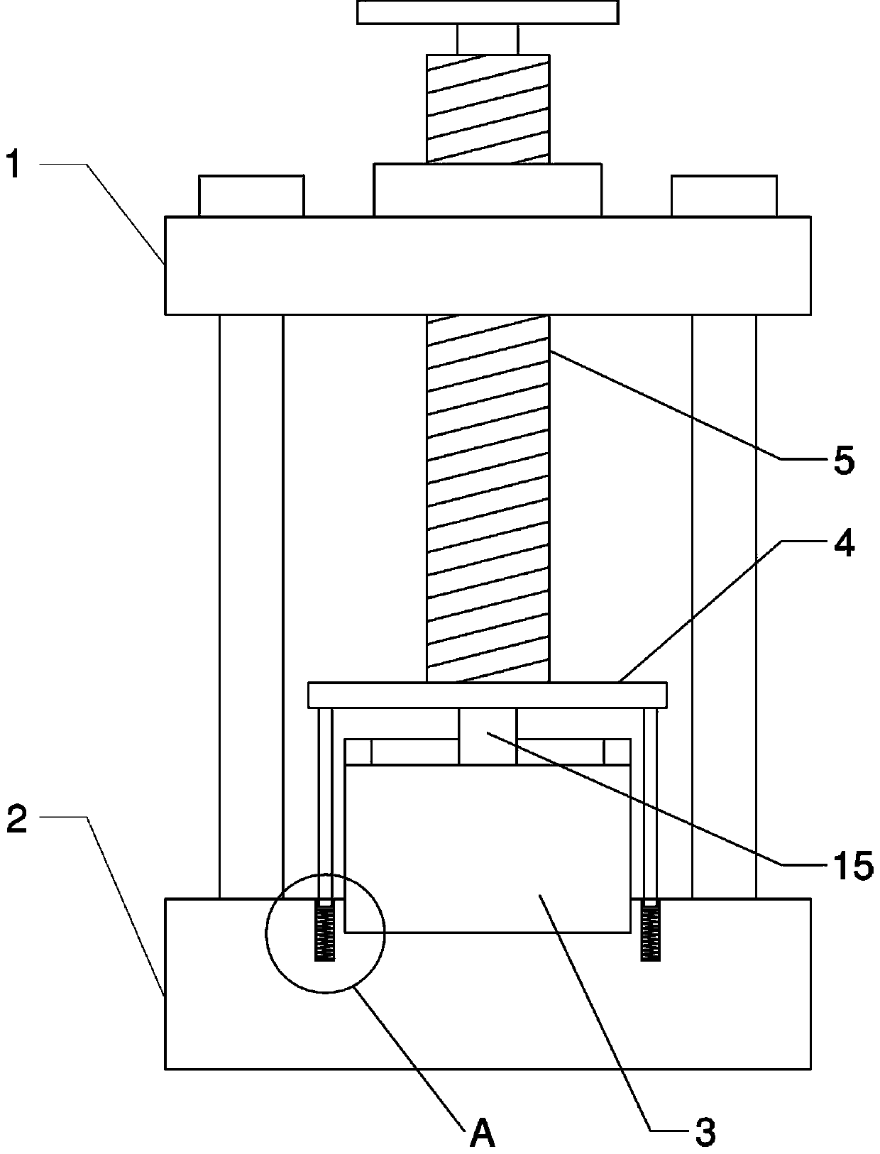
[0022] Such as figure 1 Among them, a cement compression test device includes a frame 1, the frame 1 is fixedly arranged on the base 2, the base 2 is also provided with a test block support platform 3, the frame 1 is provided with a threaded column 5, and the threaded column 5 The lower end is provided with an upper platen 4, and the upper platen 4 and the test block support table 3 are arranged on the same vertical plane;

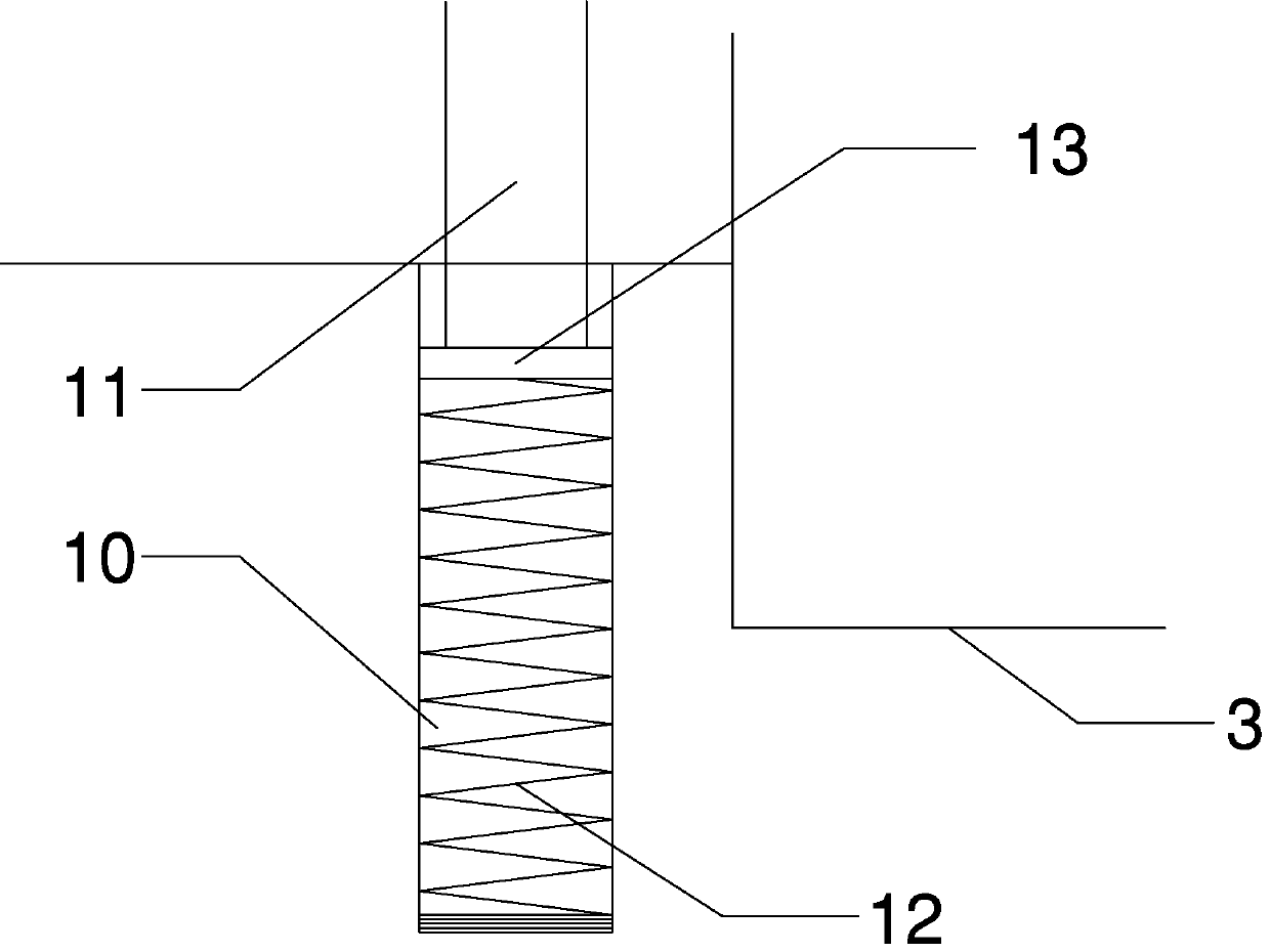
[0023] The bottom surface of the upper platen 4 is provided with a protective plate 11, the protective plate 11 adopts a cylindrical structure with a rectangular cross-section, and its cross-sectional size is larger than that of the test block support table 3, and the base 2 is provided with a groove 10 for protection. The lower end of the plate 11 can extend into the groove 10 .

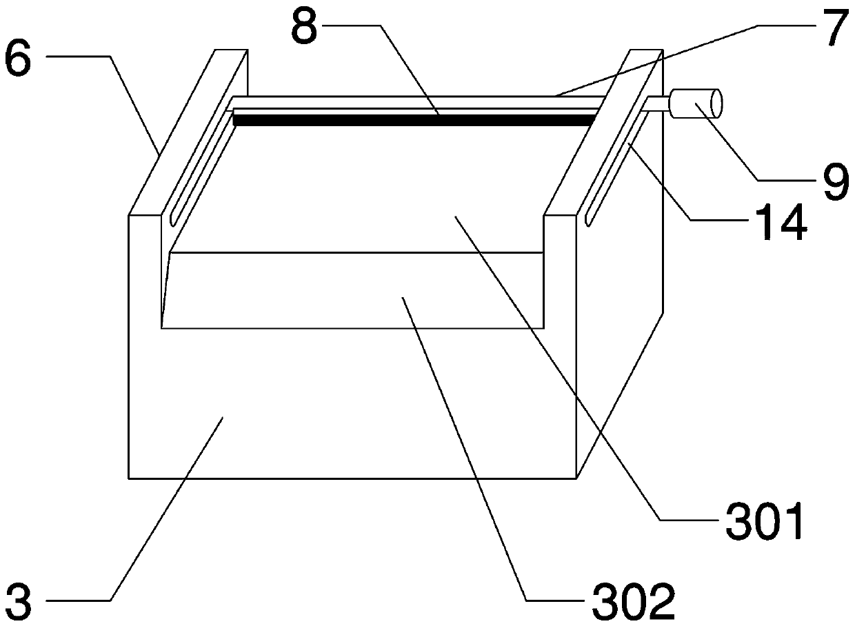
[0024] In a preferred solution, side ribs 6 are provided on both sides of the support plane 301 of the test block support platform 3, and chute 14 is provided on the side ribs ...


PUM


Abstract

The invention relates to a cement compression test device. The cement compression test device comprises a rack; the rack is fixedly arranged on a base; the base is provided with a test block supporting table; the rack is provided with a threaded column; the lower end of the threaded column is provided with an upper pressing plate; the upper pressing plate and the test block supporting table are disposed on the same vertical plane; the bottom surface of the upper pressing plate is provided with a protection plate; a groove is formed in the base; and the lower end of the protection plate can extend into the groove. According to a preferred scheme, two sides of the supporting plane of the test block supporting table are provided with side blocking edges; slide slots are formed in the side blocking edges; a sliding rod perpendicular to the two side blocking edges is arranged between the two side blocking edges; the sliding rod is disposed in the sliding slots; the sliding rod is provided with brush bristles; and one end of the supporting plane is provided with a downward inclined surface. With the above structure adopted, debris splashing which may occur when a test block is broken canbe avoided, the cleaning of the debris can be facilitated, and a user does not need to worry a condition that the debris is stuck in gaps and is difficult to clean.

Description

technical field [0001] The invention relates to the field of cement production and processing, in particular to a cement compression test device. Background technique [0002] In cement production and processing enterprises, after the cement processing is completed, it is necessary to conduct sampling inspections on the same batch of cement to ensure that the strength of the cement meets the production needs. Usually, the cement needs to undergo a compressive and flexural test, which is generally carried out with a press. Now In some tests, because the cement test block is not covered, it is easy to cause debris splashing and hurting people at the moment of cement breaking, and the debris needs to be cleaned up during subsequent inspection operations, and due to the splashing of debris, some broken Chips can get stuck in the gap between the frame and the support table, making removal very difficult. [0003] In the existing patented cement pressure testing machine (applicat...

Claims


Application Information

Patent Timeline
IPC IPC(8): G01N3/08G01N3/02
CPCG01N3/02G01N3/08
Inventor 王双林
Owner 枝江市美力坚水泥制品有限公司
Learn More