
Anti-fracture titanium alloy milling cutter

A titanium alloy, anti-fracture technology, applied in the field of mechanical processing, can solve problems such as titanium alloy milling cutter fracture, achieve the effect of improving safety and preventing debris from splashing

Pending Publication Date: 2022-01-11
苏州馨威盛切削工具有限公司
View PDF1 Cites 0 Cited by
  • Summary
  • Abstract
  • Description
  • Claims
  • Application Information

AI Technical Summary

Problems solved by technology

[0009] The purpose of the present invention is to provide an anti-fracture titanium alloy milling cutter to solve the problem that the titanium alloy milling cutter mentioned in the background technology is prone to fracture

Method used


Image

  • Anti-fracture titanium alloy milling cutter
  • Anti-fracture titanium alloy milling cutter
  • Anti-fracture titanium alloy milling cutter

Examples


Embodiment 1

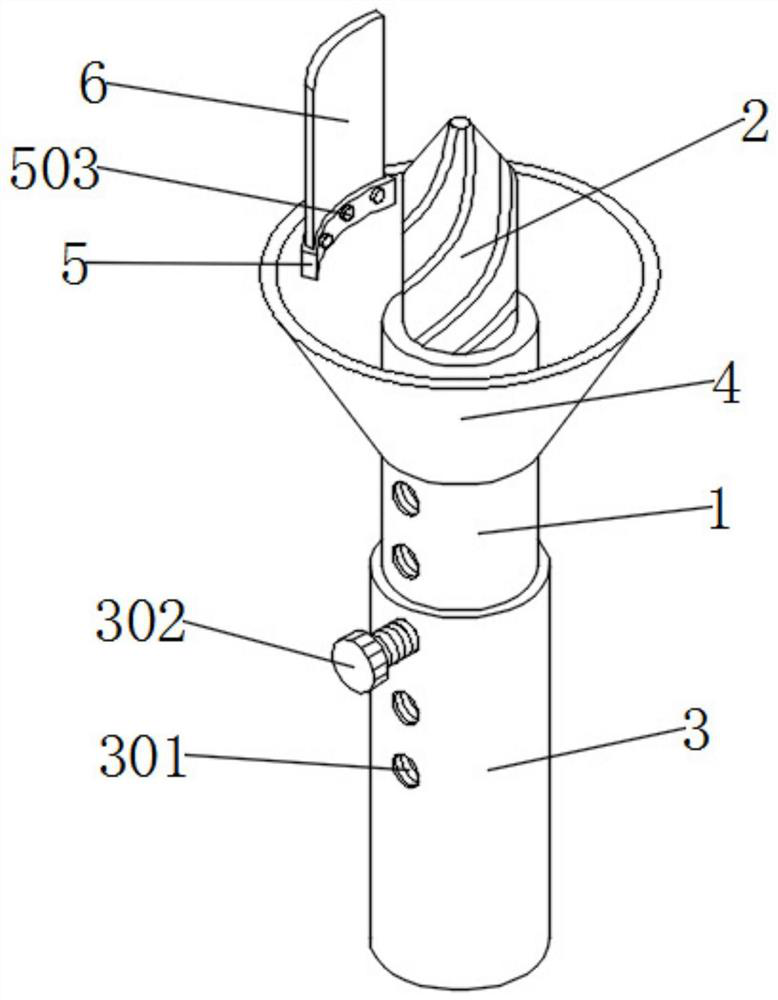
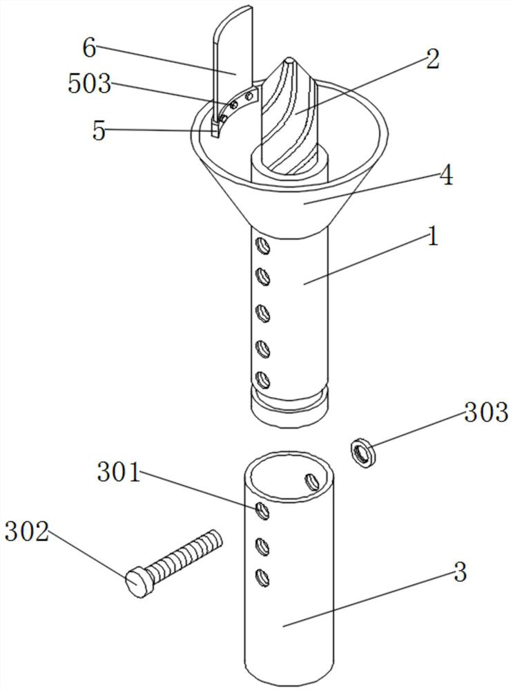
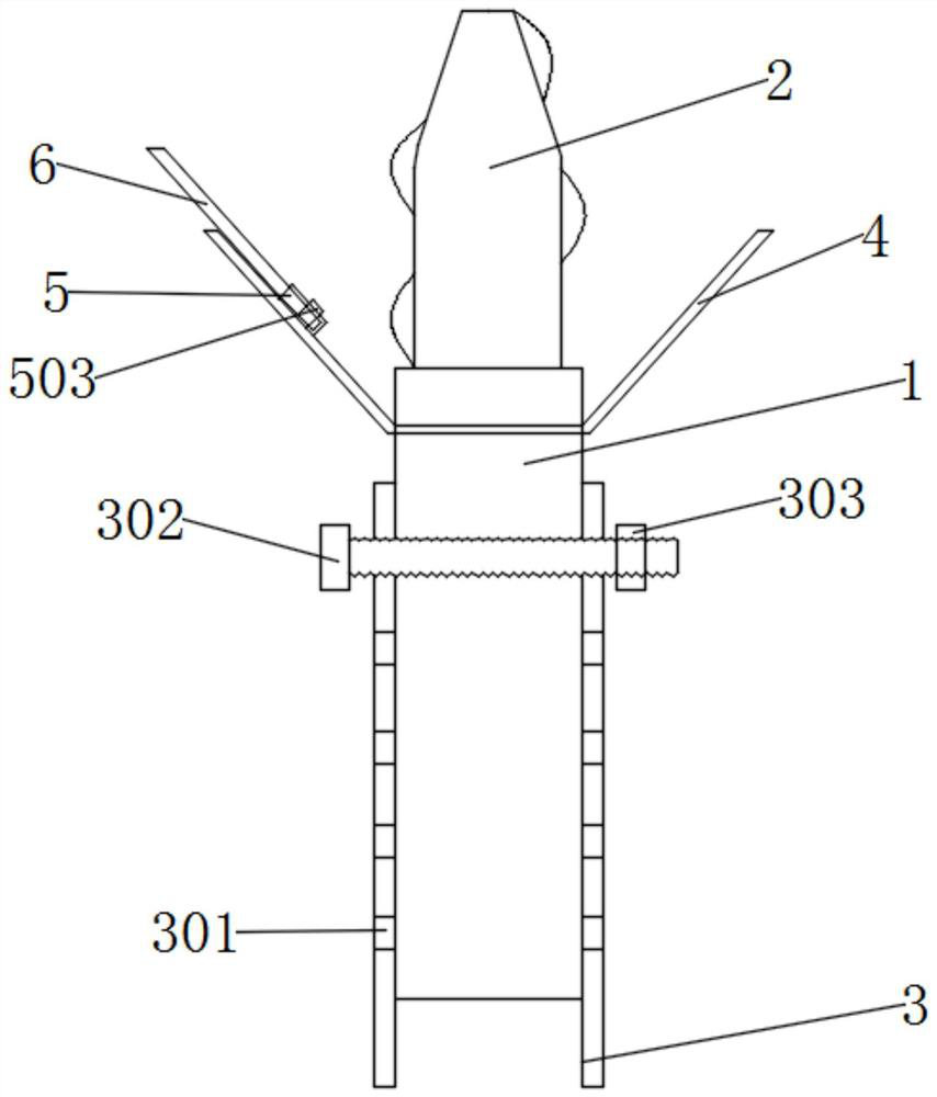
[0031] see figure 1 with figure 2 , an embodiment provided by the present invention: a fracture-resistant titanium alloy milling cutter, comprising a milling cutter body 1, a milling cutter head 2 and a protective sleeve 3, the diameter of the milling cutter main body 1 is smaller than the diameter of the protective sleeve 3, and the milling cutter The top of the main body 1 is equipped with a milling cutter head 2, and the milling cutter head 2 is located inside the shield 4, the outer surface of the milling cutter main body 1 is sleeved with a protective sleeve 3, and the outer surface of the protective sleeve 3 and the milling cutter main body 1 both penetrate A first connection hole 301 is provided, and the inner surface of the first connection hole 301 is provided with threads. The inside of the first connection hole 301 is installed with a threaded rod 302 , and one end of the threaded rod 302 is threaded with a nut 303 .

[0032] Specifically, first insert the milling...

Embodiment 2

[0034] as attached image 3 As shown, a fracture-proof titanium alloy milling cutter includes a shield 4, the shield 4 is installed on the outer surface of the milling cutter body 1, and the shield 4 is located under the protective cover 3, and the shield 4 is trumpet-shaped.

[0035] Specifically, with the high-speed rotation of the milling cutter main body 1, a part of the chips produced by the milled object will fly out under the drive of the milling cutter head 2, and when the chips fly outward, they will meet with the inside of the shield 4. The surface collides and falls on the workbench of the object to be milled, which can effectively prevent the impact of debris flying on the milling work, and to a certain extent provide convenience for subsequent workers to clean up the site.

[0036] as attached Figure 4 As shown, a kind of anti-fracture titanium alloy milling cutter includes a storage block 5 and a brush 6, a storage block 5 is installed on the inner surface of t...


PUM


Abstract

The invention discloses an anti-fracture titanium alloy milling cutter which comprises a milling cutter main body and a protective sleeve. The outer surface of the milling cutter main body is sleeved with the protective sleeve; first connecting holes are formed in the outer surfaces of the protective sleeve and the milling cutter main body in a penetrating manner, threads are arranged on the inner surfaces of the first connecting holes, and a threaded rod is mounted in the first connecting holes; and one end of the threaded rod is in threaded connection with a nut. According to the anti-fracture titanium alloy milling cutter, by installing the protective sleeve, the first connecting holes, the threaded rod and the nut, the milling cutter main body is inserted into the protective sleeve firstly, then the milling cutter main body is pulled up and down, the length of the portion, exposed out of the protective sleeve, of the milling cutter is adjusted, and then the threaded rod is connected with the first connecting holes, so that the milling cutter main body and the protective sleeve can be fixed, and the situation that the milling cutter is broken due to the fact that the exposed length of the milling cutter main body is too long can be avoided to a certain extent.

Description

technical field [0001] The invention relates to the technical field of mechanical processing, in particular to an anti-fracture titanium alloy milling cutter. Background technique [0002] A milling cutter is a rotating tool with one or more teeth used for milling. It is usually used in the machining industry. When milling an object, it uses high-speed rotation to drive the milling cutter to mill the surface of the object. During the milling process, the milling cutter usually breaks, and there are many reasons for the milling cutter breakage, among which the length of the milling cutter cannot be adjusted arbitrarily during the milling process is also one of the reasons. [0003] The defects that exist in existing titanium alloy milling cutter are: [0004] 1. Patent document CN209394054U discloses a titanium alloy milling cutter. Ten titanium alloy blades are helically fixed on the outer surface of the shaft of the same material. The diameter of the shaft is 0.4 to 0.6 ti...

Claims


Application Information

Patent Timeline
IPC IPC(8): B23C5/00B23Q11/08B23Q11/00
CPCB23C5/00B23Q11/08B23Q11/0042B23C2222/88
Inventor 王慧芬
Owner 苏州馨威盛切削工具有限公司
Learn More