
Patsnap Eureka
For R&D, Patsnap Eureka makes reading and utilizing patents & technical documents easy.
Patsnap Eureka AIR
Designed for self-driven R&D workflows. Generate viable solutions, solve complex R&D challenges, empower your innovation with AI.

Patsnap Eureka Materials
Designed for material experts only. Revolutionize your material R&D, from search, analyze, to developing new materials.

TechResearch
Generate reliable direction feasibility study reports for your R&D in just a few steps.

TechSeek
Discover and master advanced knowledge NOW. Basics, ideas, possibilities, all at once.

TechMind
As an expert in R&D Theories, TechMind can generates customized viable solutions instantly.

TechRisk
Analyze your overall solution with one click, know your potential R&D risks in advance.

TechMonitor
Get weekly tech updates, stay abreast of the latest tech innovations and key insights.
Power supply and fetching device for display rack
A technology of power taking device and display rack, which is applied in the direction of coupling device, two-part connecting device, and parts of connecting device, etc., can solve the problem of disorderly distribution of wires, and achieve the effect of avoiding the disorderly distribution of wires, meeting the needs of use, and having a reasonable design.
- Summary
- Abstract
- Description
- Claims
- Application Information
AI Technical Summary
Problems solved by technology
Method used
Image

Examples
Embodiment 1
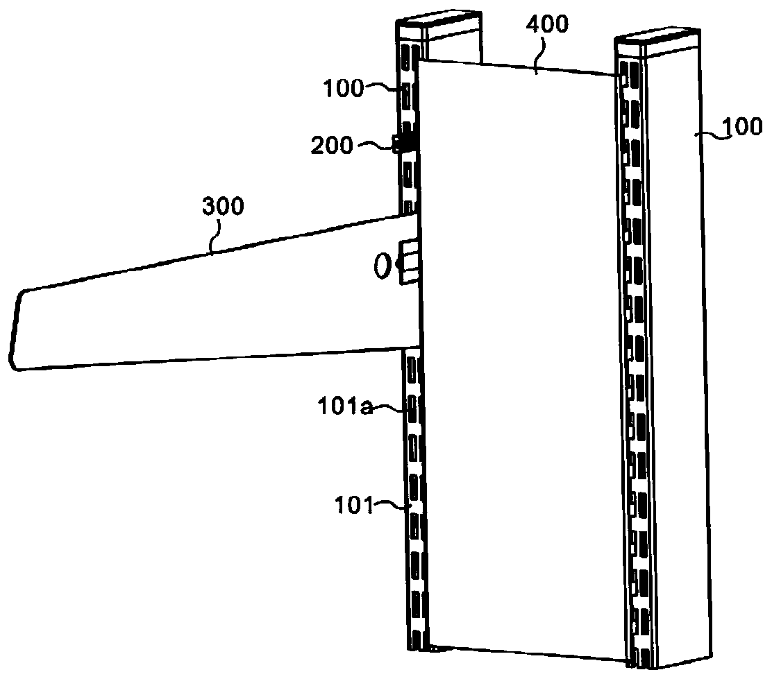
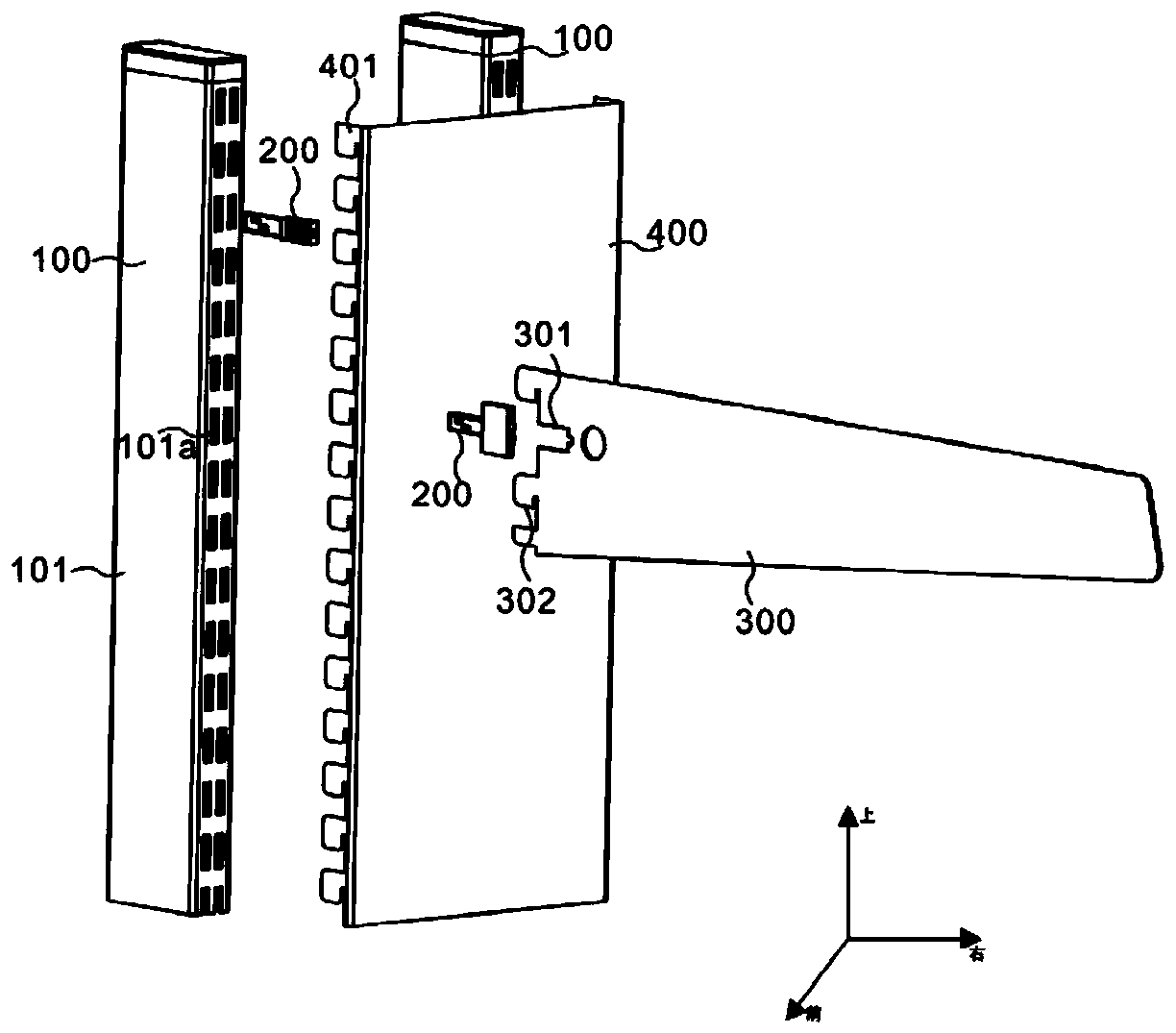
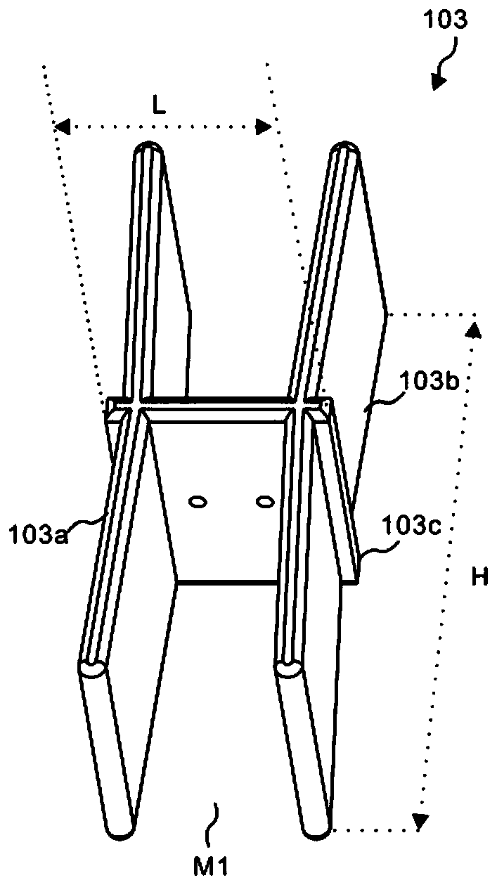
[0049] refer to figure 1 and figure 2 , provides a schematic diagram of the overall structure of the display rack power supply and take-off device, such as figure 1 A power supply and take-off device for an exhibition stand includes a power supply unit 100, including a power supply housing 101, a power transmission assembly 102, and an installation assembly 103, and the power transmission assembly 102 is arranged in the housing 101 through the installation assembly 103; and, the power take-off unit 200 passes through The single through hole 101 a of the power supply casing 101 is matched with the power supply double conductor 102 a of the power transmission assembly 102 .
[0050] Specifically, the main structure of the present invention includes a power supply unit 100 and a power take-off unit 200. Through the mutual cooperation between the set power supply unit 100 and the power take-off unit 200, the problem of messy distribution of wires when connecting wires can be avo...
Embodiment 2
[0055] like Figure 4~7 As shown, the difference between this embodiment and Embodiment 1 is that the power-taking unit 200 of the present invention includes a power-taking housing 201 and a power-taking guide 202 , and the power-taking housing 201 and the power-taking guide 202 cooperate with each other to facilitate use. Personnel take power from one side as required, avoiding the messy distribution of wires. Specifically, this embodiment takes a power taking unit 200 as an example. The power taking unit 200 includes a power taking housing 201 and a power taking guide 202. The housing 201 plays the role of protecting the power-taking guide piece 202, which is the main body to realize the power-taking, and the power-taking guide piece 202 is arranged in the power-taking cavity N1 of the power-taking housing 201; it should be noted that the power-taking The casing 201 is divided into a power-taking seat 201a and a power-taking cover 201b. The power-taking cover 201b is closed ...
Embodiment 3
[0060] like Figure 4 and Figure 5 As shown, the difference between this embodiment and Embodiment 1 and Embodiment 2 is that the power-taking housing 201 of the present invention also includes a tail cover 201c, which is a square tube structure, and the tail cover 201c is used to reinforce the power-taking base 201a and The power-taking cover 201b is snapped together, and it is convenient for the user to insert and remove the process. Specifically, the main body power-taking housing 201 also includes a tail cover 201c, and the tail cover 201c is used to reinforce the power-taking seat 201a and the power-taking cover 201b. And to facilitate the process of plugging in and out of the user, the tail cover 201c is sleeved on the periphery of the power taking seat 201a and the power taking cover 201b of the far away power taking hole 201b-1, that is, the power taking seat 201a and the power taking cover 201b are embedded in the tail In the cover 201c, preferably, the power-taking...
PUM
 Abstract
Description
Claims
Application Information
 - R&D Engineer
- R&D Manager
- IP Professional
- Industry Leading Data Capabilities
- Powerful AI technology
- Patent DNA Extraction
Browse by: Latest US Patents, China's latest patents, Technical Efficacy Thesaurus, Application Domain, Technology Topic, Popular Technical Reports.
© 2024 PatSnap. All rights reserved.Legal|Privacy policy|Modern Slavery Act Transparency Statement|Sitemap|About US| Contact US: help@patsnap.com