Signal control box for municipal traffic

A signal control and control box technology, applied in cooling/ventilation/heating renovation, modification by conduction heat transfer, support structure installation, etc. Chaotic distribution, simple and convenient installation and disassembly, and the effect of improving work efficiency

Inactive Publication Date: 2022-05-31
李保军
View PDF0 Cites 0 Cited by
  • Summary
  • Abstract
  • Description
  • Claims
  • Application Information

AI Technical Summary

Problems solved by technology

[0002] The traffic signal light is a signal light for commanding traffic operation. The traffic signal light needs to be regulated by the signal control box in the process of use. The existing signal control box has certain defects in the actual use process. Because the control unit in the signal control box Devices need to run all the time, and these control components will generate more heat. Since most of the existing control components are closely arranged, the heat dissipation is poor. If the control components are not cooled in time, it is easy to cause the control components to be damaged. Damaged by overheating, thus affecting the normal use of traffic lights
Moreover, the control components in the existing signal control box are not easy to disassemble and install. When the control components need to be repaired or replaced, it takes a lot of time for the maintenance personnel to install and disassemble, which greatly reduces the work efficiency.
Most of the connecting wires in the existing signal control box are arranged in a staggered manner, and some connecting wires are entangled together, which is difficult to sort out. At the same time, it is easy to cause a short circuit of the connecting wires, which affects the normal operation of the traffic signal lights.

Method used


Image

  • Signal control box for municipal traffic
  • Signal control box for municipal traffic
  • Signal control box for municipal traffic

Examples


Embodiment Construction

[0022] The technical solutions in the embodiments of the present invention will be clearly and completely described below with reference to the accompanying drawings in the embodiments of the present invention. Obviously, the described embodiments are only a part of the embodiments of the present invention, but not all of the embodiments. Based on the embodiments of the present invention, all other embodiments obtained by those of ordinary skill in the art without creative efforts shall fall within the protection scope of the present invention.

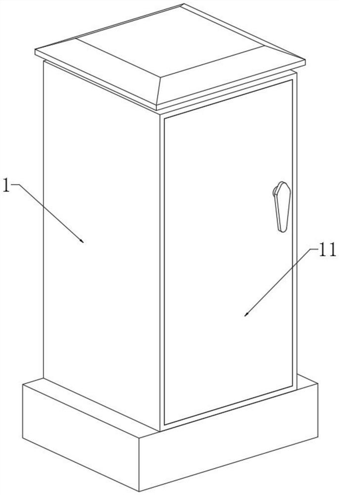
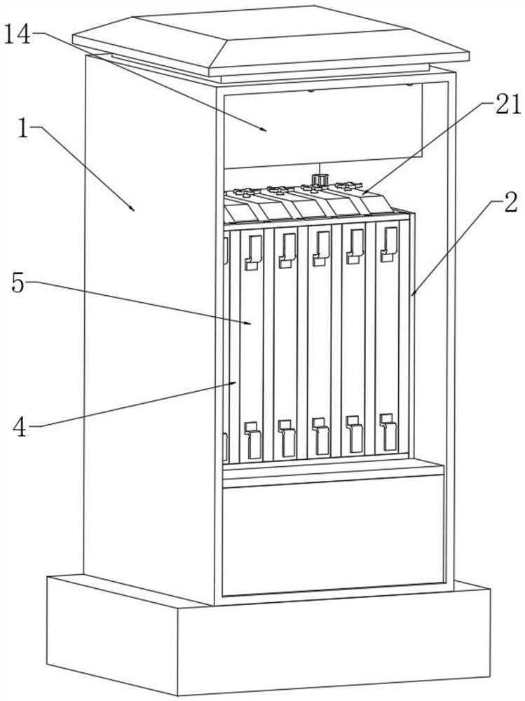
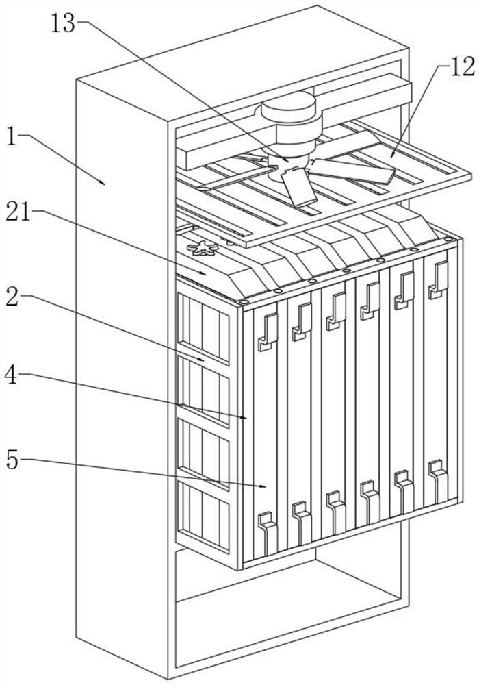
[0023] see Figure 1 to Figure 6 , the present invention provides a technical solution: a signal control box for municipal traffic, comprising a control box main body 1, the front and rear sides of the control box main body 1 are connected with a box door 11 through hinges, and the control box main body 1 is connected with a box door 11. The upper end of the cavity is welded with a ventilation baffle 12, and the upper end of the inner...


PUM


Abstract

The invention relates to the technical field of municipal traffic equipment, in particular to a signal control box for municipal traffic, which comprises a control box main body, box doors are connected to the front and rear side surfaces of the control box main body through hinges, a ventilation partition plate is welded to the upper end of an inner cavity of the control box main body, and a cooling fan is arranged at the upper end of the inner cavity of the control box main body. The device has the beneficial effects that when connecting wires at the rear end of the component main body need to be arranged and fixed, the adjusting threaded rod is rotated, the adjusting threaded rod drives the walking nut to move up and down, the walking nut drives the fixing plate to move up and down, and the connecting wires at the rear end of the component main body are arranged and fixed through bolts. The fixing plate drives the L-shaped plate and the U-shaped clamping seat to move up and down, so that the U-shaped clamping seat is adjusted to a proper position, and the connecting wires at the rear end of the component main body can be conveniently clamped and fixed, so that the connecting wires at the rear end of the component main body can be orderly arranged, and disordered distribution of the connecting wires is prevented.

Description

technical field [0001] The invention relates to the technical field of municipal traffic equipment, in particular to a signal control box for municipal traffic. Background technique [0002] The traffic signal light is a signal light that directs the traffic operation. The traffic signal light needs to be regulated by the signal control box in the process of use. The existing signal control box has certain defects in the actual use process. Due to the control element in the signal control box The device needs to run all the time, and these control components will generate a lot of heat. Since most of the existing control components are arranged in close contact, the heat dissipation is poor. If the control components are not dissipated in time, it will easily lead to the control components. Damaged due to overheating, thus affecting the normal use of traffic lights. In addition, the control components in the existing signal control box are not easy to disassemble and instal...

Claims


Application Information

Patent Timeline
Patent Type & Authority Applications(China)
IPC IPC(8): H05K7/14H05K7/20
CPCH05K7/1401H05K7/1447H05K7/20136H05K7/2039
Inventor 李保军
Owner 李保军
Why Eureka
Try Eureka