Logic control circuit of slope compensation signal in peak current mode DC-DC converter

A logic control circuit, DC-DC technology, applied in the direction of conversion equipment without intermediate conversion to AC, electrical components, output power conversion devices, etc., can solve problems affecting the transient response characteristics of the system, and achieve ideal control performance. The effect of preventing overcompensation problems

Active Publication Date: 2019-07-05
深圳市泰德半导体有限公司
View PDF13 Cites 2 Cited by
  • Summary
  • Abstract
  • Description
  • Claims
  • Application Information

AI Technical Summary

Problems solved by technology

[0003] If the peak current mode controlled DC-DC converter system works in continuous conduction mode (Continuous Conduction Mode, CCM), it is necessary to add a slope compensation signal to prevent loop oscillation; if the system is in discontinuous conduction mode (Disontinuous Conduction Mode, DCM), because the loop does not have sub-harmonic oscillation in this case, so the slope compensation signal is not needed, but the slope compensation signal that always exists will make the loop in an overcompensated state, making it by the peak current Mode control tends to change to voltage mode control in principle, which will affect the transient response characteristics of the system in this state

Method used


Image

  • Logic control circuit of slope compensation signal in peak current mode DC-DC converter
  • Logic control circuit of slope compensation signal in peak current mode DC-DC converter
  • Logic control circuit of slope compensation signal in peak current mode DC-DC converter

Examples


Embodiment Construction

[0020] The technical scheme of the present invention will be described in detail below in conjunction with the accompanying drawings.

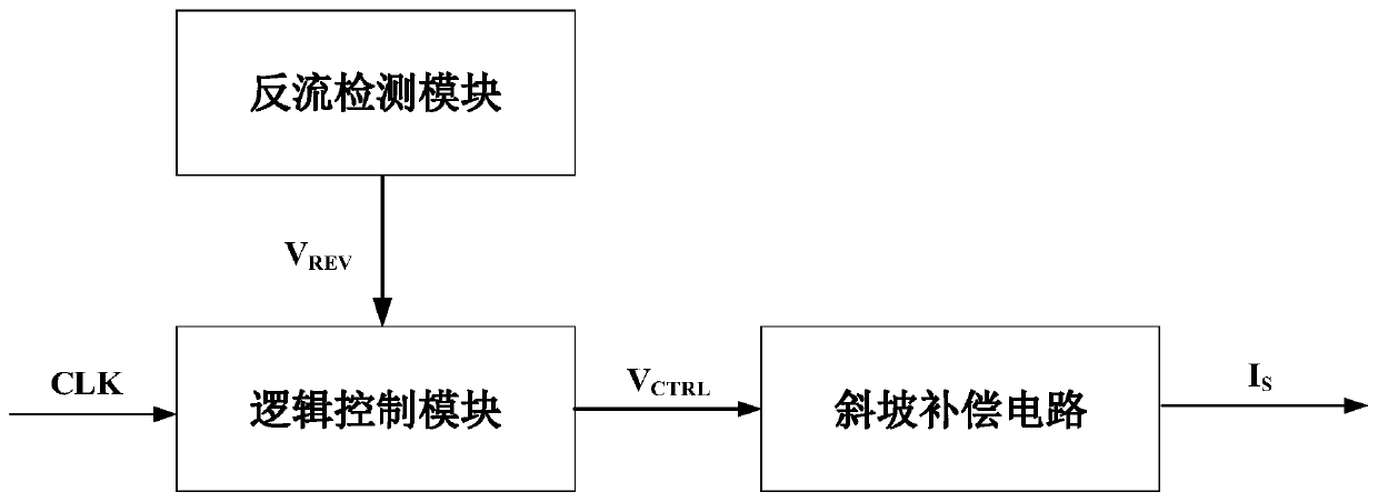
[0021] The present invention proposes a logic control circuit for a slope compensation signal in a peak current mode DC-DC converter, including a reverse current detection module and a logic control module, and the reverse current detection module provides a peak current mode DC-DC conversion circuit for the logic control module. Whether it is in the CCM or DCM working mode information, it is judged whether the peak current mode DC-DC converter is in the CCM or DCM working mode according to detecting whether the peak current mode DC-DC converter has reverse flow. When the peak current mode DC-DC converter does not reverse current, that is, when the peak current mode DC-DC converter is in the CCM working mode, the output of the reverse current detection module is always low; when the peak current mode DC-DC converter When reverse current occurs...


PUM


Abstract

The invention discloses a logic control circuit of a slope compensation signal in a peak current mode DC-DC converter, and belongs to the technical field of electronic circuits. A counter current detection module is used for detecting whether the peak current mode DC-DC converter suffers from a counter current or not, and when the peak current mode DC-DC converter suffers from the counter current,it proves that the DC-DC converter is in a DCM working mode, and the counter current detection module outputs a high level; when the counter current detection module does not detect the counter current, it proves that the DC-DC converter is in a CCM working mode, and the counter current detection module outputs a low level; a logic control module carries out detection on the rising edge of each clock period of the DC-DC converter according to the judgment of the DC-DC converter working mode by the counter current detection module, wherein when the DC-DC converter is in the CCM mode, the DC-DCconverter is controlled to output the slope compensation signal as normal; and when the DC-DC converter is in the DCM mode, the slope compensation signal of the DC-DC converter is eliminated, so thatthe problem of over-compensation of the peak current mode system during DCM can be effectively prevented, and the DC-DC converter has an ideal peak current mode control performance.

Description

technical field [0001] The invention belongs to the technical field of electronic circuits and relates to a logic control circuit for controlling the generation of slope compensation signals in a peak current mode DC-DC conversion circuit. Background technique [0002] In the DC-DC converter application of peak current mode control, in order to prevent sub-harmonic oscillation in the system loop, a slope compensation signal will be added. There are mainly three existing slope compensation methods: fixed slope slope compensation, segmented slope compensation and adaptive slope compensation. However, the existing slope compensation circuit does not include other logic control circuits, so the slope compensation signal will always be generated; the slope compensation signal and the inductor current sampling signal are superimposed and compared with the output of the error amplifier, and then the control signal of the circuit is obtained. [0003] If the peak current mode contr...

Claims


Application Information

Patent Timeline
Patent Type & Authority Applications(China)
IPC IPC(8): H02M3/10
CPCH02M3/10H02M1/0003
Inventor 罗萍王晨阳周先立黄龙
Owner 深圳市泰德半导体有限公司
Why Eureka
Try Eureka