
Vane type cam phaser

A cam phaser, vane technology, applied in the direction of machine/engine, engine components, mechanical equipment, etc., can solve the problems of small vane width, inability to meet miniaturization, increasing the weight and volume of rotor and vane cam phasers, etc. Achieve the effect of satisfying high torsion-compression ratio and high adjustment angle

Inactive Publication Date: 2019-07-09
SCHAEFFLER TECH AG & CO KG
View PDF6 Cites 0 Cited by
  • Summary
  • Abstract
  • Description
  • Claims
  • Application Information

AI Technical Summary

Problems solved by technology

One is to arrange the locking unit on the rotor base of the rotor. Since the locking unit is not arranged on the blades, the width of the blades is made smaller in this way, and five working chambers can be established between the rotor and the stator, and the torque-compression ratio is also high. It can be greater than 4Nm / bar, but the diameter of the rotor base cannot be set too small due to the locking unit, thus increasing the overall weight and volume of the rotor and vane cam phaser, which cannot meet the needs of product miniaturization

Method used


Image

  • Vane type cam phaser
  • Vane type cam phaser
  • Vane type cam phaser

Examples


Embodiment Construction

[0019] In view of the technical problems existing in the prior art, the present invention provides a new type of vane cam phaser, so that the size of the rotor base and vanes can be designed according to needs without being limited by the size of the locking unit, so that the vane cam phase can be achieved. The miniaturization of the device meets the requirements of high torsion-pressure ratio and high adjustment angle.

[0020] In order to make the above-mentioned objectives, features and beneficial effects of the present invention more obvious and understandable, specific embodiments of the present invention will be described in detail below in conjunction with the accompanying drawings.

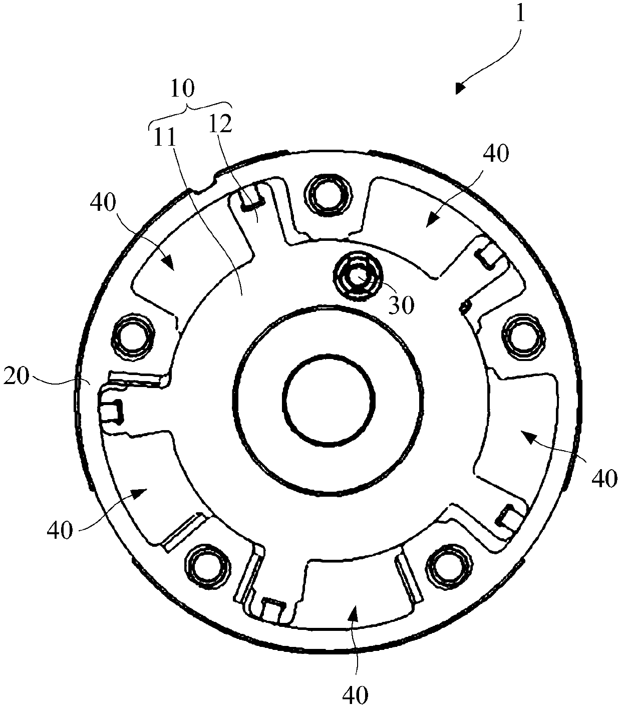
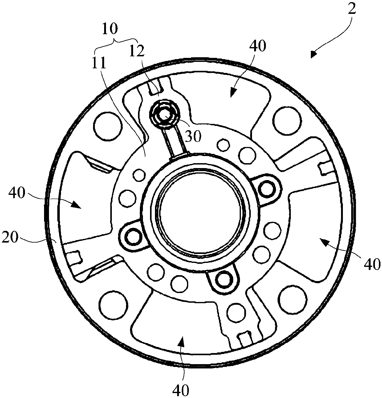
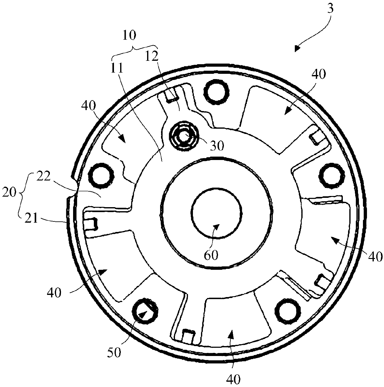
[0021] reference figure 1 , An existing vane type cam phaser 1, which includes a rotor 10 and a stator 20, the rotor 10 is installed in the stator 20 and the rotor 10 and the stator 20 are coaxial. The rotor 10 includes a rotor base 11 and five blades 12 distributed in the circumferential direc...


PUM


Abstract

The invention discloses a vane type cam phaser. The vane type cam phaser comprises a rotor, a stator and a locking unit. The rotor comprises a rotor base and a plurality of vanes, and the vanes are distributed in the circumferential direction of the rotor base. The rotor is mounted in the stator and the rotor and the stator are coaxial. The locking unit is disposed at the joint of the rotor base and the vanes for locking the rotation of the rotor relative to the stator. By arranging the locking unit at the joint of the rotor base and the vanes, the miniaturization of the vane type cam phaser is realized while meeting the high twist-compression ratio requirement.

Description

Technical field [0001] The invention relates to the technical field of automobile engines, in particular to a vane type cam phaser. Background technique [0002] The vane type cam phaser acts on the vane by internal oil pressure to make it deflect, and realizes the stepless adjustment of the phase angle. The locking unit on the vane type cam phaser fully guarantees its reliability when the engine is started and idling. The most widely used variable valve mechanism in automotive engines at home and abroad. [0003] There are two common arrangements for the locking unit on the existing vane cam phaser. One is to arrange the locking unit on the rotor base of the rotor. Since the locking unit is not arranged on the blade, the width of the blade is made small in this way. Five working chambers can be established between the rotor and the stator, and the torsion-pressure ratio is also It can be greater than 4Nm / bar, but the diameter of the rotor base body cannot be set too small due to...

Claims


Application Information

Patent Timeline
Patent Type & Authority Applications(China)
IPC IPC(8): F01L1/344
CPCF01L1/344
Inventor 敖颖文何艳桦
Owner SCHAEFFLER TECH AG & CO KG
Learn More