

Test reference system of crank dynamometer
A reference system and power meter technology, which is applied in the calibration/testing of force/torque/power measuring instruments, measuring devices, instruments, etc., can solve the problems of easy operation accuracy and low efficiency of operators, and achieve reasonable design and improved Operational efficiency, efficiency improvement effect
- Summary
- Abstract
- Description
- Claims
- Application Information
AI Technical Summary
Problems solved by technology
Method used
Image

Examples
Embodiment 1
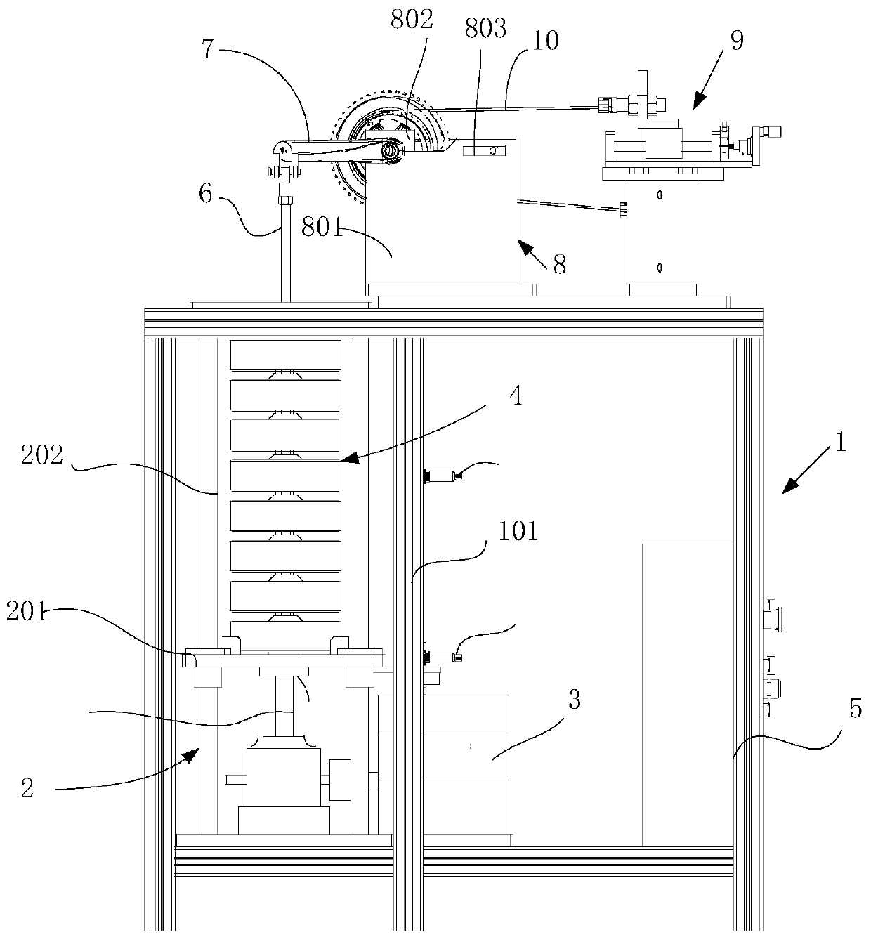
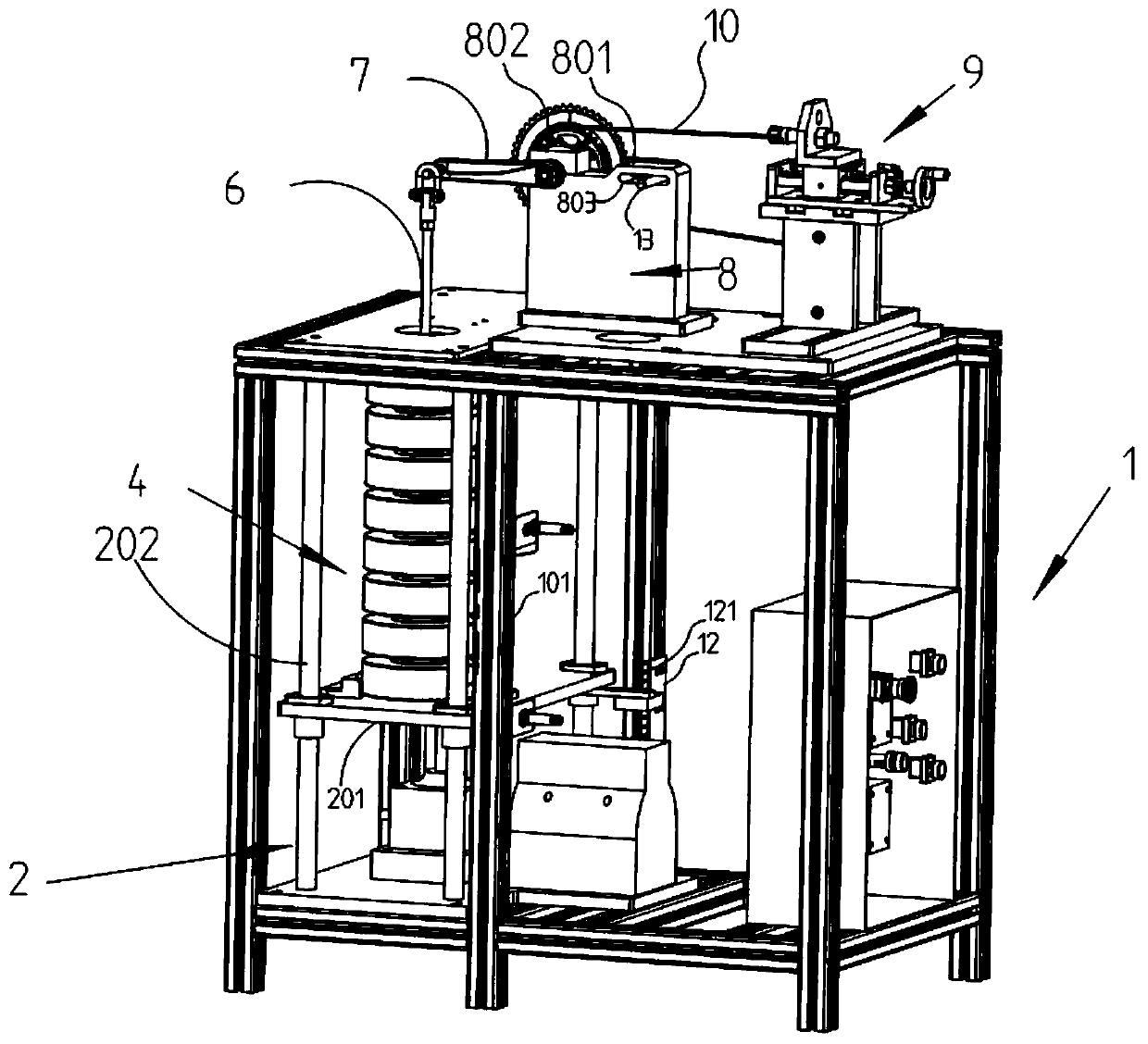
[0037] Embodiment one, reference figure 1 and figure 2 , The benchmark system for crank dynamometer testing in this embodiment includes: a main frame 1 , a lifting platform 2 , a motor 3 , a weight set 4 , a suspension rod 6 , a chain crank mounting system, and an electronic control unit 5 .
[0038] The main frame 1 includes a whole frame composed of cross bars and six vertical bars 101. The six vertical bars 101 divide the space in the frame into two parts. The left side is the weight group 4 lifting part, and the right side is the electric control part, including To drive the electric control unit 5 of the motor. A chain crank mounting system is installed on the main frame 1.
[0039] The lifting table 2 is used to support the weight group 4, including a supporting plate 201, a vertical sliding rod 202, the supporting plate 201 is set on the vertical sliding rod 202, the bottom of the supporting plate 201 is a top plate 204, and the top plate 204 is connected with the dr...
Embodiment 2
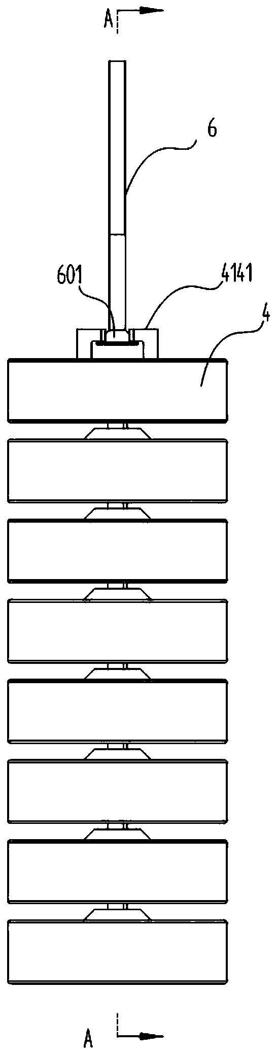
[0043] Embodiment two, refer to image 3 and Figure 4 , the present embodiment proposes a weight set 4, including a weight body 41 and a suspension structure 414. The bottom of the weight body 41 has a concave platform 411; , or be set as a hanging structure 414; the middle part has a movable cavity 412 connected with the concave platform portion 411; the hanging structure 414 includes a stopper and a fixed part, the stopper can move up and down in the movable cavity, and the fixed part Fix it on the boss of another weight.
[0044] The weights in the weight group 4 are stacked on each other when placed, and the uppermost weight needs to be hung on the bottom of the suspension rod 6, so the uppermost weight is set as the hanging structure 414, and the design of the hanging structure 414 should be consistent with the hanging structure 414. Cooperate with the bottom end of the rod, a hook can be set at the bottom end of the suspension rod 6, and a matching collar can be set a...
Embodiment 3
[0048] Embodiment three, refer to Figure 5 and Figure 6 , the present embodiment proposes a chain crank mounting system, including a crank horizontal fixing tool 8 and a chain tensioning table 9, the crank horizontal fixing tool 8 includes a tool body 801, a pressing block 802 and a horizontal hole 803, and the crank 7 passes through the pressing block 802 It is movably installed on the frock body 801. After adjusting the level, one end hangs the weight through the suspension rod 6, and the other end is fixed by the horizontal positioning shaft 12 inserted into the horizontal hole. Chain tensioning platform 9 comprises: support seat 91 and the sliding seat 92 above it, and sliding seat 92 comprises fixed block 921, slide block 922, block 923, locking device 924 and rotary handle 925 successively from left to right, leading screw 93 one end is fixed on the fixed block 921, and connects the rotating handle 925 after passing through the slide block 922 and the stop block 923. ...
PUM
 Abstract
Description
Claims
Application Information