

Voltage fluctuation resistant delay switch circuit based on rising edge sampling
A delay switch, anti-voltage technology, applied in the field of electronics, can solve the problems of short delay, narrow tunable range, abnormality, etc., and achieve the effect of rapid power-on and wide tunable range of delay
- Summary
- Abstract
- Description
- Claims
- Application Information
AI Technical Summary
Problems solved by technology
Method used
Image


Examples
Embodiment Construction
[0038] The embodiments of the present application provide a voltage fluctuation-resistant delay switch circuit based on rising edge sampling to solve the technical problems of the prior art that the delay switch circuit has short delay, narrow tunable range, and slow rising edge of power on.
[0039] In order to better understand the above technical solutions, the above technical solutions will be described in detail below in conjunction with the accompanying drawings and specific implementation methods. It should be understood that the embodiments of the present invention and the specific features in the embodiments are detailed descriptions of the technical solutions of the present application. , rather than limiting the technical solutions of the present application, the embodiments of the present application and the technical features in the embodiments can be combined without conflict.
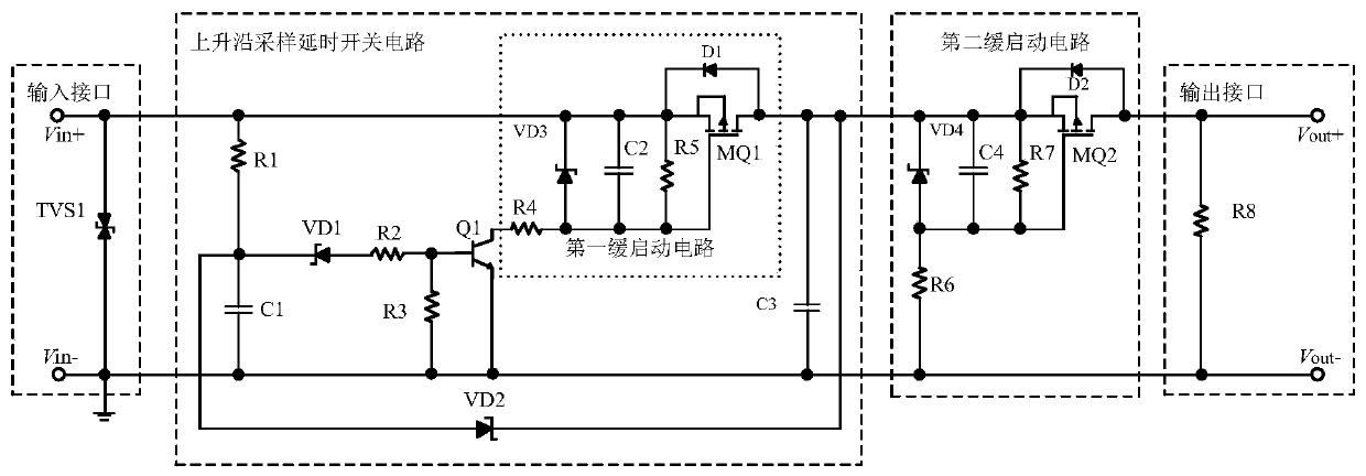
[0040] see figure 1 , a delay switch circuit based on rising edge sampling to resist ...
PUM
 Abstract
Description
Claims
Application Information