Device and method for detecting and/or examining an abrasion on the surface of a cylindrical component

A cylindrical and component technology, applied in the direction of measuring devices, using optical devices, reducing greenhouse gases, etc., can solve the problems of time-consuming, damage, etc., and achieve the effect of low cost and low equipment technology consumption

Active Publication Date: 2019-07-09
フラマトムゲゼルシャフトミットベシュレンクテルハフツング
View PDF4 Cites 4 Cited by
  • Summary
  • Abstract
  • Description
  • Claims
  • Application Information

AI Technical Summary

Problems solved by technology

However, this method has the following drawbacks: the part to be tested must be sufficiently accessible from all sides to be able to guide the probe over its surface, and the probe does not have an infinitely small radius in order not to cause damage to the part by the scanning itself
However, this method is very time-consuming, as the impression must be removed from the component, for example in the fuel element cooling pool of a nuclear power plant, and the evaluation is usually carried out in a hot cell outside the nuclear power plant

Method used


Image

  • Device and method for detecting and/or examining an abrasion on the surface of a cylindrical component
  • Device and method for detecting and/or examining an abrasion on the surface of a cylindrical component
  • Device and method for detecting and/or examining an abrasion on the surface of a cylindrical component

Examples


Embodiment Construction

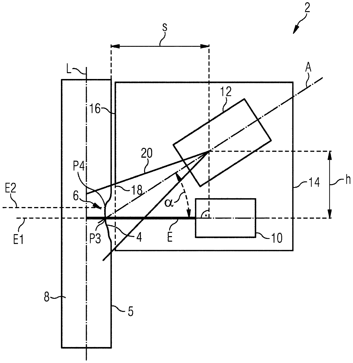
[0032] figure 1 A device 2 for detecting and inspecting wear 4 that occurs on a surface 5 of a cylindrical part 8 is shown. The cylindrical part 8 is currently the fuel rod of a pressurized water reactor. The device 2 comprises a light source 10 which projects light onto a surface region 6 of a cylindrical part 8 in which wear 4 has occurred. The light source 10 is a slit lamp which emits light in the beam plane E and illuminates the surface region 6 with this light. In order to detect an image of the surface area 6 illuminated by the light beam, the device 2 has an image detection unit 12 in the form of a camera. The optical axis A of the image detection unit 12 is oriented at an angle α to the beam plane E. As shown in FIG. The current angle α is about 35°. Furthermore, the image detection unit 12 is arranged at a distance h above the beam plane E, wherein the distance h relates to the point at which the optical axis A of the image detection unit 12 intersects the outer ...


PUM


Abstract

The invention relates to a device (2) and a method for detecting and/or examining an abrasion (4) on the surface of a cylindrical component (8), in particular of a rod-shaped component of a nuclear power plant, in particular a fuel rod, a control rod, a neutron source rod, an absorber rod, and/or a lance, comprising a light source (10) for projecting light onto a surface region (6) of the cylindrical component (8), and an image capturing unit (12), in particular a camera for capturing an image of the surface region (6) on which light is being projected and/or for examining the surface region (6) of the cylindrical component (8). The light source (10) is a split lamp which emits light on a light emission plane (E), and the optical axis (A) of the image capturing unit (12) is oriented at anangle (alpha) relative to the light emission plane (E) of the light source (10).

Description

technical field [0001] The invention relates to a device and a method for detecting and / or inspecting wear on the surface of cylindrical components, in particular rod-shaped components of or used in nuclear power plants, in particular fuel rods, control rods, neutron Source rods, absorber rods and / or spray guns. Background technique [0002] On the surfaces of cylindrical or rod-shaped components employed in nuclear technology installations or nuclear power plants, damage in the form of material abrasion can occur, for example, suddenly as a result of temperature fluctuations, material fatigue, material overloading or continuously during operation of nuclear technology installations Chipping off of the surface of the component, e.g. due to material corrosion, removal (Fredding) or influences from secondary bodies. This wear can affect the safety-relevance of the component and thus its ability to be used, making it necessary to assess the degree of wear on the surface of the...

Claims


Application Information

Patent Timeline
Patent Type & Authority Applications(China)
IPC IPC(8): G21C17/06G01B11/24
CPCG21C17/06G01B11/255G01B11/25Y02E30/30
Inventor 沃尔夫冈·赫梅尔
Owner フラマトムゲゼルシャフトミットベシュレンクテルハフツング
Why Eureka
Try Eureka