
Drag wheel lift

An elevator and wheel-type technology, which is applied to elevators, hoists, transportation and packaging in buildings, can solve the problems of increasing construction costs, and achieve the effect of saving construction space and reducing support force

Inactive Publication Date: 2003-01-29
KONE CORP
View PDF3 Cites 0 Cited by
  • Summary
  • Abstract
  • Description
  • Claims
  • Application Information

AI Technical Summary

Problems solved by technology

As a dedicated space, the computer room generally increases construction costs

Method used


Image

  • Drag wheel lift
  • Drag wheel lift
  • Drag wheel lift

Examples


Embodiment Construction

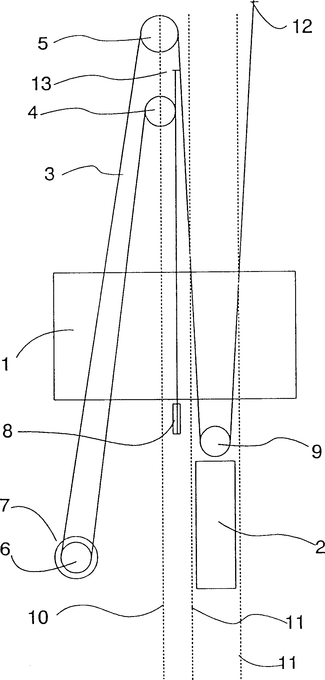
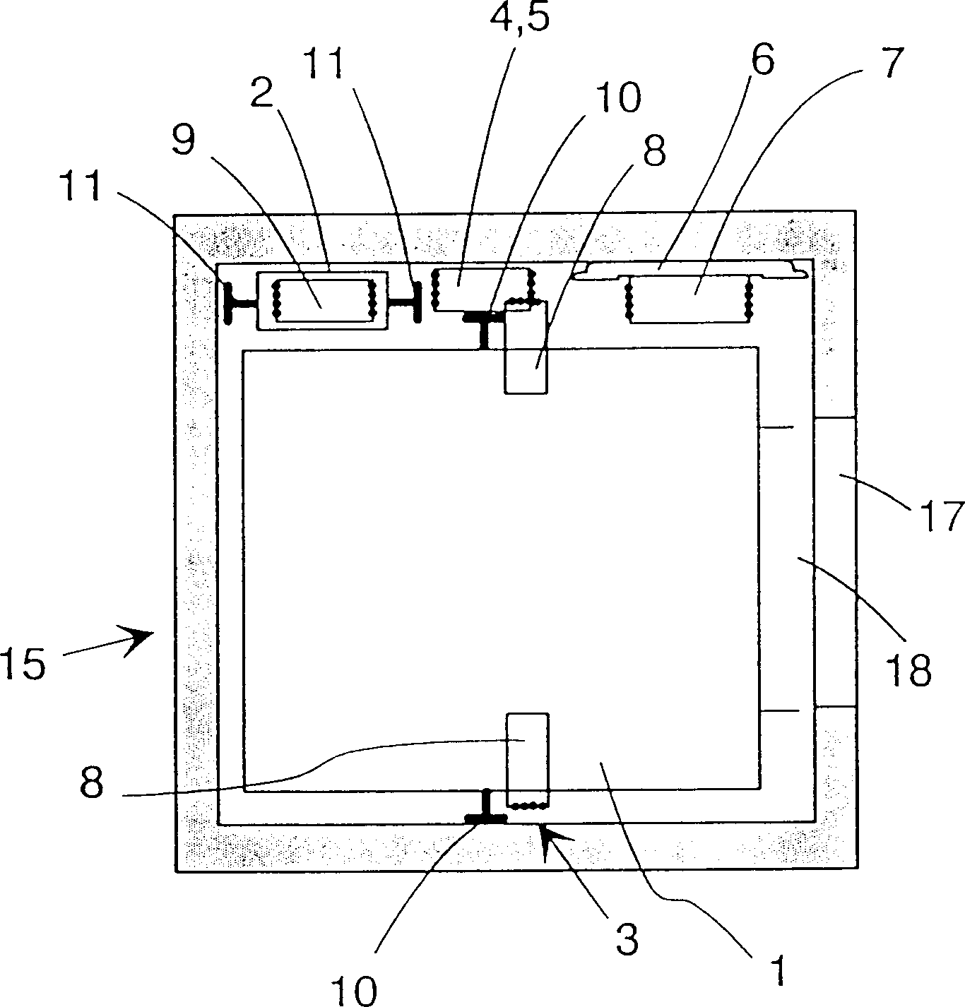
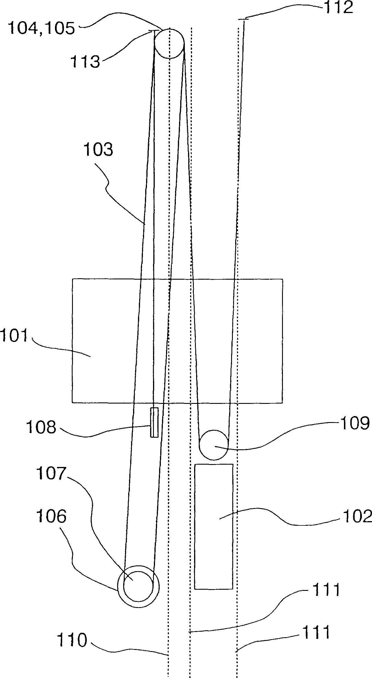
[0018] figure 1 It is a schematic diagram of a drag wheel elevator provided by the present invention. The elevator is a drag wheel elevator with a machine underneath. Both the elevator box 1 and the counterweight 2 are suspended on the cables 3 of the elevator. The elevator car 1 , suspended from the cables 3 , is substantially centered or symmetrical with respect to a vertical line passing through the center of gravity of the elevator car 1 . Likewise, the counterweight 2 is suspended from the cable 3 so as to be substantially centered or symmetrical with respect to a vertical line passing through the center of gravity of the counterweight 2 . The drive machine unit 6 of the elevator is placed in the elevator shaft, preferably in the lower part of the elevator shaft, while the cables 3 lead to the elevator box 1 and the counterweight 2 via diverting pulleys 4, 5 placed in the upper part of the elevator shaft. In most cases, the hawser consists of multiple parallel ropes, u...


PUM


Abstract

Traction sheave elevator in which the drive machinery (6) together with the traction sheave (7) is placed in the elevator shaft (15). The hoisting ropes (3) go upward from the traction sheave (7). In the cross-section of the elevator shaft, the vertical projections of the elevator car (1,101), counterweight and the traction sheave (7) of the drive machinery are separate from each other.

Description

technical field [0001] The invention relates to a drag wheel elevator. Background technique [0002] Efficient and economical use of building space has always been one of the objectives in the development of elevators. In conventional drag sheave driven elevators, the machine room or other space for accommodating the elevator drive machinery occupies a considerable portion of the building space required for the elevator. The problem is not only the amount of space required to drive the machine, but also its arrangement. There are many different solutions for arranging computer rooms, but they generally involve considerable constraints on architectural design, at least in terms of space utilization and appearance. For example, a side drive elevator with a machine room below requires a machine room or machine room to be located next to the elevator shaft, typically on the lowest floor of the building. As a dedicated space, the computer room generally increases construction ...

Claims


Application Information

Patent Timeline
Patent Type & Authority Patents(China)
IPC IPC(8): B66B7/06B66B11/00B66B11/04B66B11/08
CPCB66B11/0045B66B11/08B66B11/008
Inventor 埃斯科·奥兰科哈里·哈卡拉乔玛·马斯塔拉蒂
Owner KONE CORP
Learn More