Water gun device

A water gun and body technology, applied in spraying devices, single handheld devices, etc., can solve the problems of unpredictable flushing time, no stable place for water guns, etc., and achieve easy access, easy installation and disassembly, and easy operation Effect

Pending Publication Date: 2019-07-12
苏州市中医医院
View PDF0 Cites 0 Cited by
  • Summary
  • Abstract
  • Description
  • Claims
  • Application Information

AI Technical Summary

Problems solved by technology

[0003] The purpose of the present invention is to provide a water gun device to solve the problem that the water gun has no stable place and the time for flushing cannot be predicted in the background art

Method used


Image

  • Water gun device
  • Water gun device
  • Water gun device

Examples


Embodiment 1

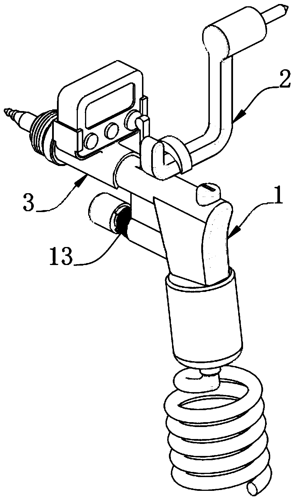
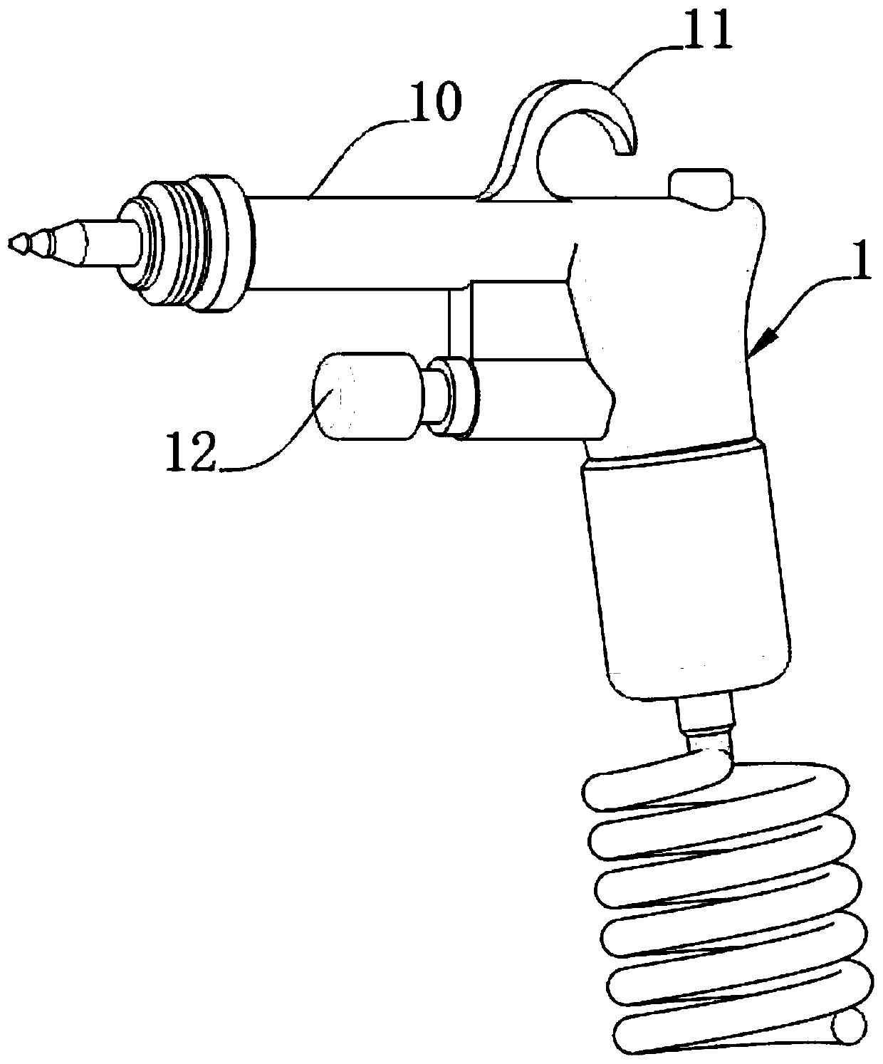
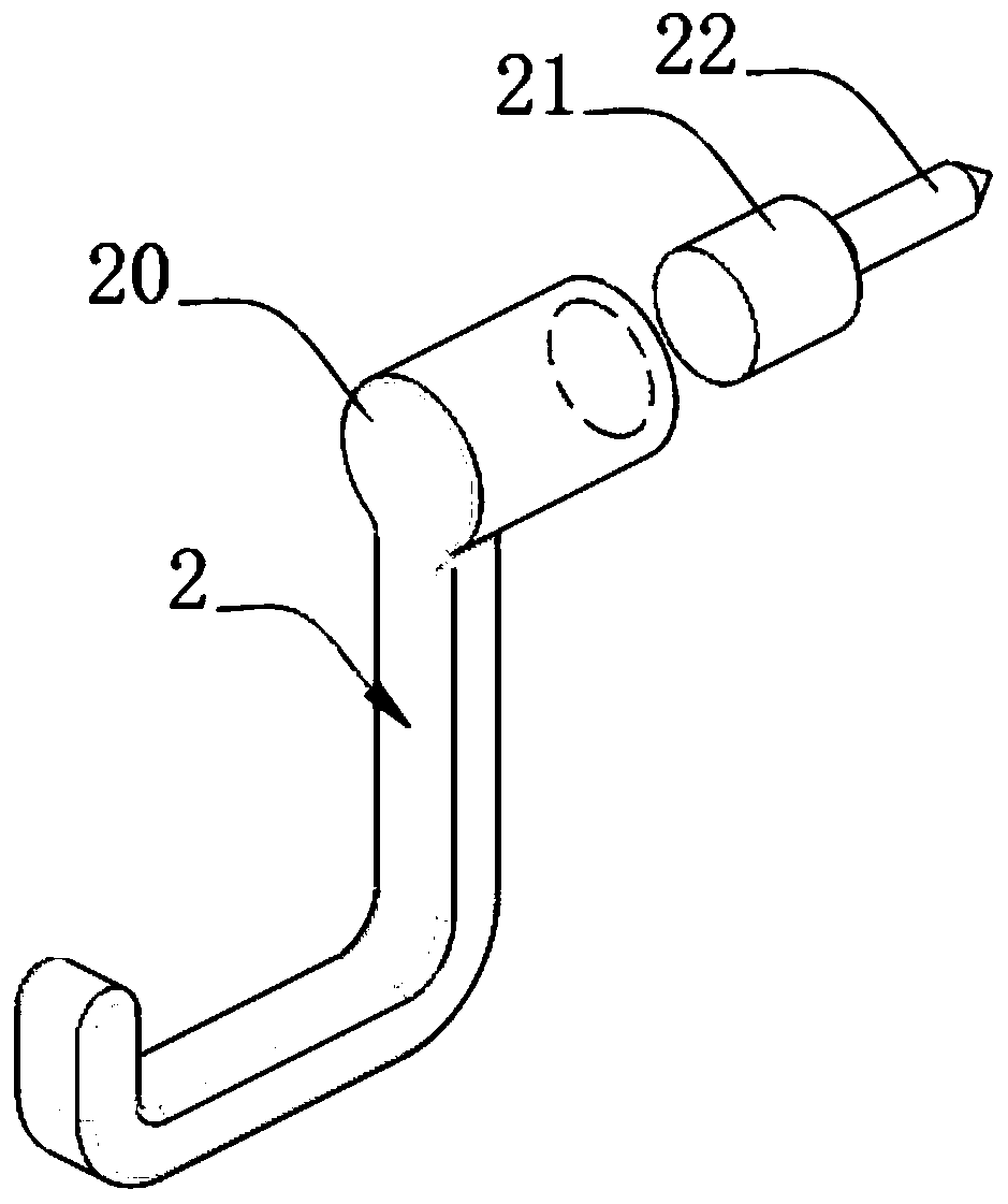
[0026] A water gun device. In order to facilitate the placement of the water gun body 1 conveniently and stably, the inventor sets a fixing hook 2 as a preferred embodiment, such as figure 1 , figure 2 with image 3 As shown, the water gun body 1 is included. A fixed hook 2 is provided above the water gun body 1. The water gun body 1 includes a water gun tube 10, the top side of the water gun tube 10 is welded with an arc-shaped hook 11, and a trigger 12 is installed on one side of the water gun body 1 A spring 13 is sleeved on one side of the trigger 12, a sleeve 20 is provided on the top of the fixed hook 2, a sleeve post 21 is inserted into the inner side of the sleeve 20, and a pointed post 22 is embedded at one end of the sleeve post 21.

[0027] In this embodiment, the fixing hook 2 is made of PP, that is, polypropylene, which is light in weight, good in toughness, and rigid in strength. The pointed post 22 is made of iron material, and the sleeve post 21 and the pointed pos...

Embodiment 2

[0031] As a second embodiment of the present invention, in order to facilitate the timing of flushing, the inventor has provided a timing seat 3 as a preferred embodiment, such as Figure 4 , Figure 5 , Image 6 with Figure 7 As shown, one side of the fixed hook 2 is provided with a timing seat 3, the top surface of the timing seat 3 is provided with a clamping plate 30, one end of the timing seat 3 is provided with a rotating column 31 outside, and one side of the rotating column 31 is provided with a linkage rod 32 , The bottom end of the linkage rod 32 is provided with a collar 320, the collar 320 is snap-fitted with the trigger 12, the middle section of the linkage rod 32 is provided with a swivel 321, the swivel 321 is inserted into the pivot 31, and the top of the linkage rod 32 An arc block 322 is provided on one side.

[0032] In this embodiment, the timing seat 3 is made of PP material, namely polypropylene, which is light in weight, good in toughness, and rigid in str...


PUM


Abstract

The invention relates to the technical field of mechanical devices, in particular to a water gun device. The water gun device comprises a water gun body, a fixing hook is arranged above the water gunbody, a timing seat is arranged on one side of the fixing hook, a sleeve is arranged at the top end of the fixing hook, a sleeve column is inserted into the inner side of the sleeve, a sharp column isembedded into one end of the sleeve column, a clamping plate is arranged on the top surface of the timing seat, a rotary column is arranged on the outer side of one end of the timing seat, a linkagerod is arranged on one side of the rotary column, a sleeve ring is arranged at the bottom end of the linkage rod, and a rotary ring is arranged at the middle section of the linkage rod. According to the water gun device, the sharp column is nailed on the wall surface, and then the fixing hook is connected to the sleeve column in a sleeving mode for stability so that an arc-shaped hook of the watergun body can be directly hung on the fixing hook, then stable placement is achieved, moreover, taking is convenient, when a water gun trigger is pressed, the linkage rod is enabled to rotate around the rotary column, and then the arc-shaped block touches a start button of a timer so that timing can be performed, the water gun device is convenient to operate, and the flushing time can be observedfrom the front side conveniently.

Description

Technical field [0001] The invention relates to the technical field of mechanical devices, in particular to a water gun device. Background technique [0002] At present, similar high-pressure water guns commonly used in clinical departments and disinfection supply centers are used for flushing and disinfection. Some instruments, such as Da Vinci precision instruments, need water gun flushing for more than 30 seconds to achieve the cleaning effect. You can only estimate the time artificially or use the second timer during work, which is not conducive to the operation, and the cleaning quality cannot be grasped in real time. This smart water gun can accurately control the time. The staff in the supply room can fully grasp the time when the Da Vinci precision instruments are flushed, and meet the flushing requirements in the instructions; the quality tracer in the supply room can also bring up information to grasp the cleaning quality of the staff in the department in real time, an...

Claims


Application Information

Patent Timeline
IPC IPC(8): B05B11/00B05B15/60B05B12/00
CPCB05B11/00B05B15/60B05B12/002
Inventor 石磊吴谐
Owner 苏州市中医医院
Why Eureka
Try Eureka