
A tool setting method for machining terahertz slow wave structural parts

A slow-wave structure and terahertz technology, applied in the direction of metal processing machinery parts, metal processing, metal processing equipment, etc., can solve the problems of low processing efficiency, clamping error, etc., and achieve the goal of improving tool setting accuracy and shortening tool setting time Effect

Active Publication Date: 2021-04-20
HARBIN INST OF TECH
View PDF15 Cites 0 Cited by
  • Summary
  • Abstract
  • Description
  • Claims
  • Application Information

AI Technical Summary

Problems solved by technology

[0005] In order to solve the problem of low processing efficiency due to the clamping error of the traditional mechanical tool setting method and the need for tool setting once for each sample processing, the present invention further provides a method for processing terahertz slow wave structural parts. tool setting method

Method used


Image

  • A tool setting method for machining terahertz slow wave structural parts
  • A tool setting method for machining terahertz slow wave structural parts
  • A tool setting method for machining terahertz slow wave structural parts

Examples


specific Embodiment approach 1

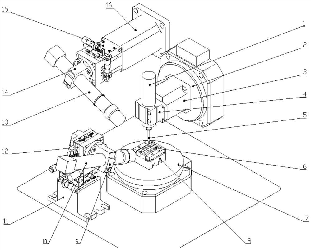
[0041] Specific implementation mode one: as figure 1 As shown, the steps of the tool setting method for processing terahertz slow wave structural parts in this embodiment are as follows:

[0042] Step 1. Establishment and calibration of the coordinate system:

[0043](1) According to the Lagrangian method, take the main body of the machine tool as the benchmark, and establish an absolute coordinate system (X, Y, Z) at the intersection of the horizontal worktable and the A-axis rotation axis as the origin;

[0044] (2) With the plane where the horizontal CCD camera 10 is located as the YOZ plane, the plane where the suspended CCD camera 13 is located is the XOZ plane, and a Cartesian coordinate system is established, and the position of the horizontal CCD camera 10 and the suspended CCD camera 13 clamping points, the position of the fixture Carry out three-dimensional calibration, and then clamp the workpiece 6, define the tool setting control body determined according to the ...

specific Embodiment approach 2

[0051] Specific implementation mode two: as figure 1 As shown, the terahertz slow wave structure processing tool setting device adopted by the tool setting method in this embodiment includes an electric spindle 1, a C-axis rotary table 2, an electric spindle support frame 3, an electric spindle chuck 4, and a hard micro milling cutter 5. Work piece 6, A-axis rotary table 7, chuck body 8, horizontal CCD chuck 9, horizontal CCD camera 10, horizontal CCD camera positioning block 11, horizontal CCD camera fine-tuning module 12, suspension CCD camera 13, suspension CCD camera Chuck 14, suspended CCD camera fine-tuning module 15 and suspended CCD camera positioning block 16; The horizontal CCD camera is connected with the horizontal CCD camera fine-tuning module 12 through the horizontal CCD chuck 9, and the suspended CCD camera is connected with the suspended CCD camera through the suspended CCD camera chuck 14 The fine-tuning module 15 is connected, the horizontal CCD camera fine-...

specific Embodiment approach 3

[0052] Specific implementation mode three: as figure 1 As shown, the horizontal CCD camera 10 of this embodiment is a 10-million-pixel variable magnification camera. Such a design can realize precise tool setting in the ultra-precision micro-milling process of the folded waveguide slow-wave structure in the low-frequency terahertz band, and the error is controlled within the range of 0.3um. Other compositions and connections are the same as those in Embodiment 1 or 2.


PUM


Abstract

A tool setting method for processing terahertz slow wave structural parts, which relates to a tool setting method. The invention solves the problem that the traditional mechanical tool setting method has a clamping error in the tool setting, and the tool setting needs to be performed once for each sample processing, and the processing efficiency is low. Step 1. Establishment and calibration of the coordinate system: Step 2. Accurate tool setting combined with absolute motion and relative motion: After completing the establishment of the coordinate system and calibration of the initial value of the position parameters of the camera, the fixture body, and the workpiece, the two The horizontal and vertical pixels of the image obtained on the camera are calibrated; according to the tool speed and acceleration parameters set in the CNC system, combined with the time characteristic curve of the calibrated pixels in multiple tool-pass experiments, the simultaneous tool setting process is obtained. Predict its motion state; use software compensation or reduce the zoom to achieve precise tool setting; step 3, error calibration and compensation. The invention is used for tool setting of a device for processing terahertz slow wave structural parts.

Description

technical field [0001] The invention relates to a tool setting method for a micro-milling machine tool, in particular to a tool setting method for processing terahertz slow wave structural parts. Background technique [0002] Traveling wave tube is the most important electric vacuum power device in electronic equipment and weaponry. It has the characteristics of small size, large loss, and high collimation, which puts forward high requirements for device processing and system integration. The slow-wave structure is the core component of the traveling wave tube, and its submillimeter mesoscopic size determines that its processing equipment and technology are very complicated; at the same time, in order to ensure the reliable operation of the system, the size deviation of the slow-wave circuit is usually required to be less than 10%. The extremely small skin depth of electromagnetic waves in the terahertz frequency band also puts forward higher requirements for the processed s...

Claims


Application Information

Patent Timeline
Patent Type & Authority Patents(China)
IPC IPC(8): B23Q15/22H01J23/24
CPCB23Q15/22H01J23/24
Inventor 陈明君鲁义凡吴春亚程健刘赫男王廷章韩鹏宇
Owner HARBIN INST OF TECH
Learn More