
Eureka
For R&D, Eureka makes reading and utilizing patents & technical documents easy.
Eureka AIR
Designed for self-driven R&D workflows. Generate viable solutions, solve complex R&D challenges, empower your innovation with AI.

Eureka Materials
Designed for material experts only. Revolutionize your material R&D, from search, analyze, to developing new materials.

TechResearch
Generate reliable direction feasibility study reports for your R&D in just a few steps.

TechSeek
Discover and master advanced knowledge NOW. Basics, ideas, possibilities, all at once.

TechMind
As an expert in R&D Theories, TechMind can generates customized viable solutions instantly.

TechRisk
Analyze your overall solution with one click, know your potential R&D risks in advance.

TechMonitor
Get weekly tech updates, stay abreast of the latest tech innovations and key insights.
Binding structure
A belt and actuating piece technology, applied in the direction of flexible slender elements, packaging, transportation and packaging, etc., can solve the problems of poor anti-theft, easy to touch or touch by mistake, easy to fail, etc., and achieve simple structure and reasonable design. , the effect of reducing the cost of use
- Summary
- Abstract
- Description
- Claims
- Application Information
AI Technical Summary
Problems solved by technology
Method used
Image


Examples
Embodiment 1
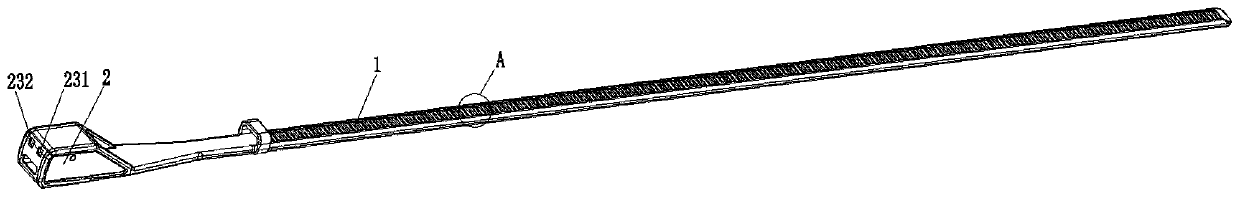
[0036] see Figure 1 to Figure 7 , the binding structure of this embodiment includes a belt body 1 , a head portion 2 and a locking portion 3 .
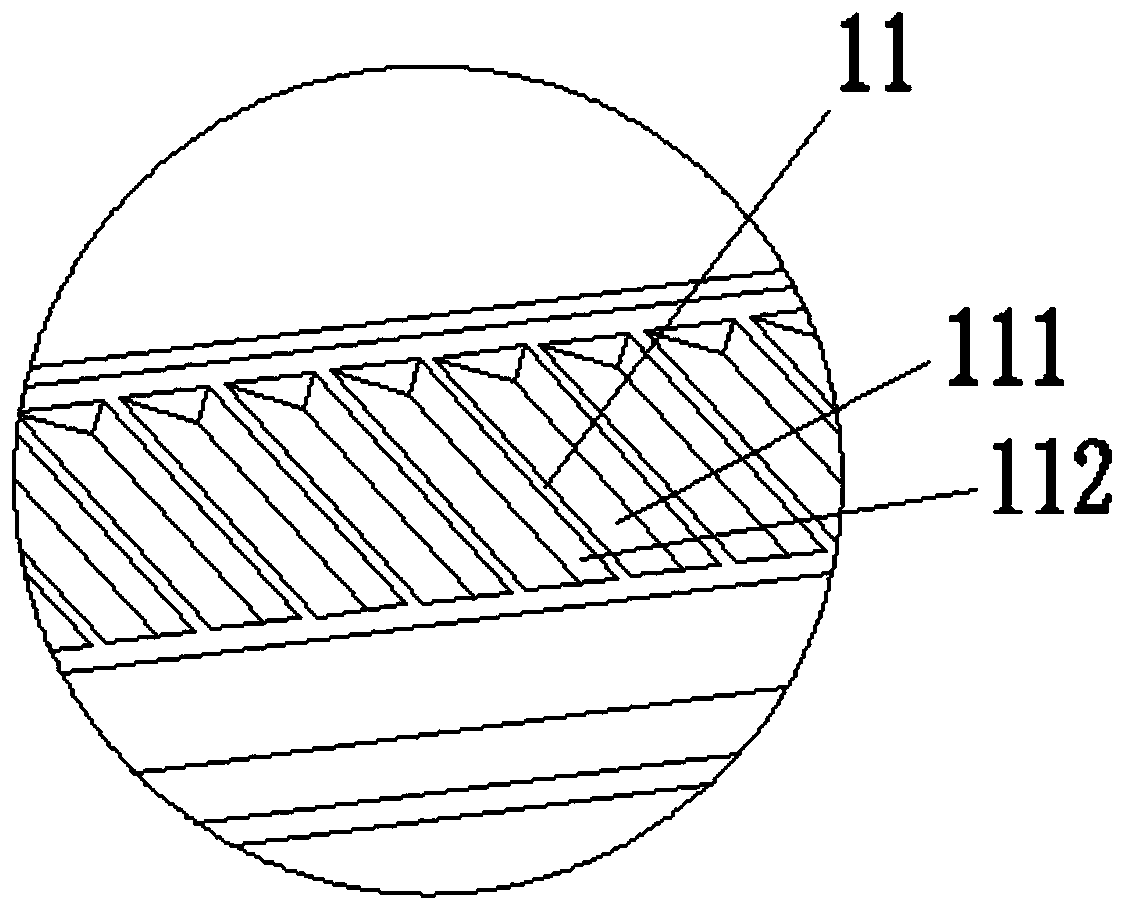
[0037] The belt body 1 in the present embodiment has flexibility or elasticity, thus, the belt body 1 can be bent and deformed, and the belt body 1 adopts materials with the above-mentioned characteristics in the prior art, such as any material in nylon, plastics, and stainless steel. One or a combination thereof, the belt body 1 is provided with several tooth portions 11 on its outer surface, specifically, the belt body can be provided with the tooth portions 11 on its front and back sides, so as to provide multiple connection methods, and several tooth portions The portion 11 is arranged along the longitudinal direction of the belt body 1 . Several tooth portions 11 can be continuous or arranged at intervals. The tooth portion 11 has a first surface 111 and a second surface 112 , the angle between the first surface and the belt b...
Embodiment 2
[0057] Such as Figure 8 As shown, the basic structure of the binding structure in this embodiment is the same as that in Embodiment 1, the difference is the structure of the actuator 31 . The actuator 31 in this embodiment has an integrated structure, that is to say, the actuator 31 is a single component, which is different from the structure of the actuator 31 in Embodiment 1 (the actuator 31 in Embodiment 1 It includes two parts, the first actuator 301 and the second actuator 302). Both the first unlocking portion 3121 and the second unlocking portion 3122 are disposed on the actuator 31 .
PUM
 Abstract
Description
Claims
Application Information
 - R&D Engineer
- R&D Manager
- IP Professional
- Industry Leading Data Capabilities
- Powerful AI technology
- Patent DNA Extraction
Browse by: Latest US Patents, China's latest patents, Technical Efficacy Thesaurus, Application Domain, Technology Topic, Popular Technical Reports.
© 2024 PatSnap. All rights reserved.Legal|Privacy policy|Modern Slavery Act Transparency Statement|Sitemap|About US| Contact US: help@patsnap.com