High-pressure fuel pump

A high-pressure pump and fuel technology, applied in fuel injection pumps, fuel injection devices, liquid fuel engines, etc., can solve problems such as inability to ensure correct dosage, damage, and unexpected noise

Inactive Publication Date: 2019-07-12
CONTINENTAL AUTOMOTIVE GMBH
View PDF9 Cites 0 Cited by
  • Summary
  • Abstract
  • Description
  • Claims
  • Application Information

AI Technical Summary

Problems solved by technology

Due to this fluctuation, filling losses can occur in the fuel high-pressure pump, so that the correct dosing of the fuel quantity required in the combustion chamber cannot be ensured
The resulting pressure p

Method used


Image

  • High-pressure fuel pump
  • High-pressure fuel pump
  • High-pressure fuel pump

Examples


Embodiment Construction

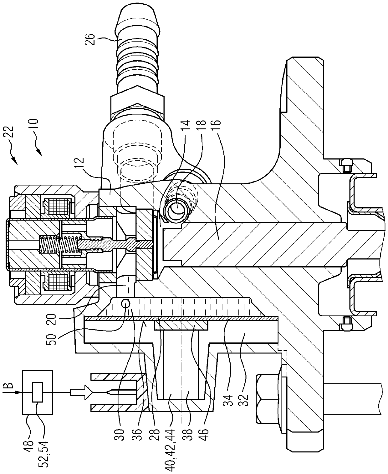
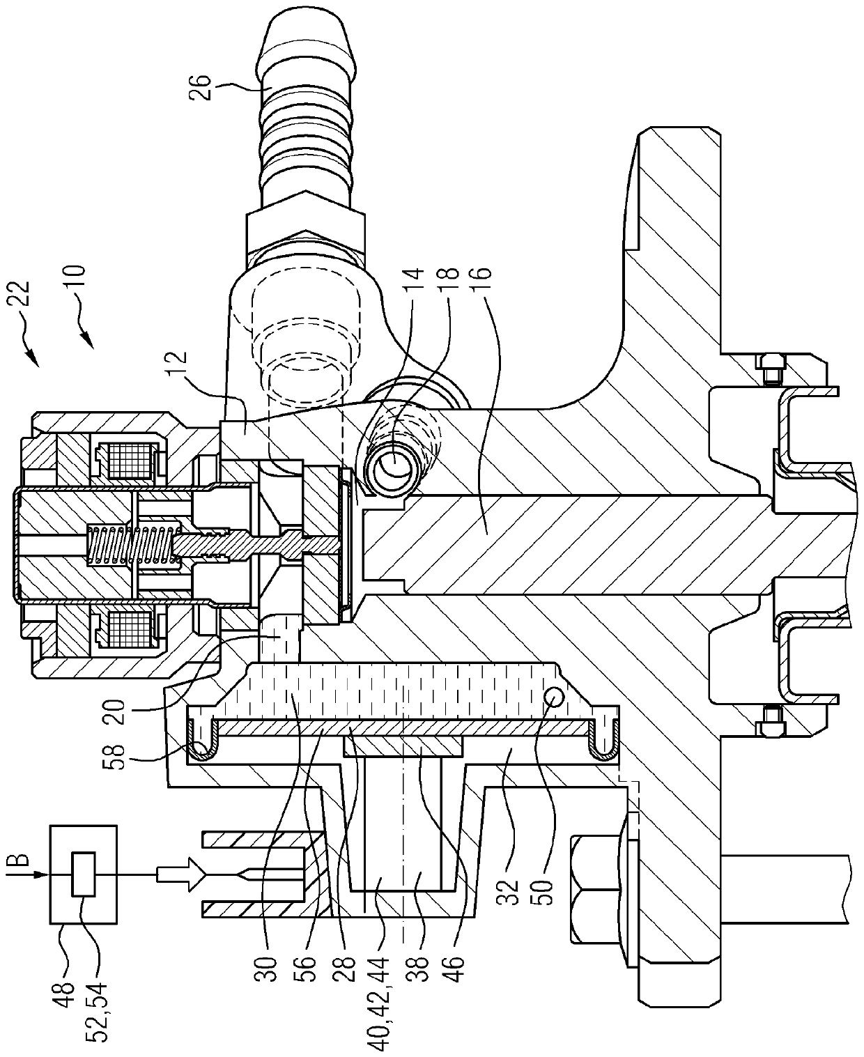
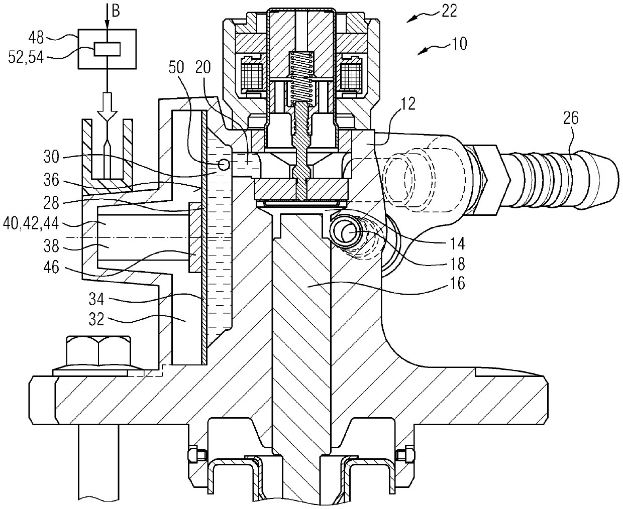
[0031] figure 1 A longitudinal section through a first embodiment of a high-pressure fuel pump 10 is shown with a housing 12 in which a pressure chamber 14 is formed. A pump piston 16 is guided in the housing 12 , which cyclically increases and decreases the volume of the pressure chamber 14 by means of a translational movement. In this case, the fuel arranged in the pressure chamber 14 is subjected to high pressure. The high-pressure fuel is then conducted further to downstream elements via the high-pressure connection 18 on the high-pressure fuel pump 10 .

[0032] Fuel is delivered from the low-pressure region 20 of the high-pressure fuel pump 10 to the pressure chamber 14 . In the closed state, the valve device 22 separates the pressure chamber 14 from the low-pressure region 20 . The low-pressure area 20 is delimited by the housing 12 of the high-pressure fuel pump 10 , the valve arrangement 22 and the supply line 26 , via which fuel is delivered to the high-pressure f...


PUM


Abstract

The invention relates to a high-pressure fuel pump (10) with a low-pressure area (20). In order to change the volume (30), the low-pressure area is defined by a sealing element (28), which can be offset from a still position. An adjustable adjusting element (38) interacts with the sealing element (28) so as to adjust the volume (30) of the low-pressure area (20) according to the needs.

Description

technical field [0001] The invention relates to a high-pressure fuel pump for applying high pressure to fuel in a fuel injection system of an internal combustion engine. Background technique [0002] High-pressure fuel pumps are used in fuel injection systems for injecting fuel into the combustion chamber of an internal combustion engine to apply high pressure to the fuel, wherein the pressure lies, for example, in the range of 150 bar to 400 bar in gasoline internal combustion engines and in the range of 1500 bar to 2500 bar in diesel internal combustion engines Inside. The higher the pressure generated in the respective fuel, the lower the emissions that are formed during the combustion of the fuel in the combustion chamber, which is advantageous especially against the background of the ever-increasing desire to reduce emissions. [0003] In order to be able to obtain a high pressure in the respective fuel, the fuel high-pressure pump is usually designed as a piston pump,...

Claims


Application Information

Patent Timeline
IPC IPC(8): F02M59/44
CPCF02M59/44F02M2200/09F02M2200/315F02M37/0041F02M55/04F02M59/366F02M2200/16F02M2200/26F04B1/053F04B7/0076F04B11/0033F02M59/442F02M59/466F16L55/04F02M59/025F02M59/34F04B37/12F04B53/002
Inventor Y.米哈伊洛夫Y.库尔特
Owner CONTINENTAL AUTOMOTIVE GMBH
Why Eureka
Try Eureka